


Бренды
Directional servo-valves in 4-way variant 4WSE3E 32

Directional servo-valves in 4-way variant 4WSE3E 32
-
Size 32
-
Component series 5X
-
Maximum operating pressure 315 bar
-
Maximum flow 1800 l/min
- Valve to control position, force, pressure or velocity
- 3-stage servo valve with electrical position control of the control spool of the 3rd stage, position sensing of the control spool by means of an inductive position transducer
- 2-stage pilot control valve of size 6 with high dynamics
- 1st stage nozzle/flapper plate amplifier
- Filter for 1st stage freely accessible and replaceable from the outside
- For subplate mounting: Porting pattern according to ISO 4401
- Can also be used as 3-way version
- Valve and integrated control electronics are adjusted and tested
- Optimized valve control loop
- High response sensitivity, very low hysteresis and zero point drift
- Internal or external pilot oil supply and pilot oil return available
- Gap seals at pressure chambers of the control sleeve, no O-ring wear
|
Type |
4WSE3E | ||
|
Nenngröße |
32 | ||
|
Geräteserie |
5X | ||
|
Porting pattern |
according to ISO 4401 | ||
|
Einbaulage |
any - if it is ensured that the pilot control is supplied with sufficient pressure (> 10 bar) during start-up of the system. In case of insufficient pressure supply, the control spool of the servo valve can take any position. This may result in channel P being connected to the actuator and the pressure build-up being delayed. This may be prevented by providing an external pressure supply at port X. | ||
|
Storage temperature range |
°C |
-20 … +80 | |
|
Masse |
kg |
35 | |
|
Ambient temperature range |
°C |
-20 … +60 | |
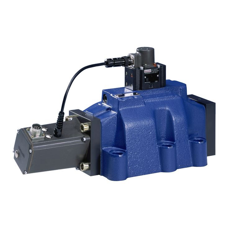
Valves of type 4WSE3E... are electrically operated, 3-stage directional servo valves. They are mainly used to control position, force or pressure and velocity.
These valves consist of a 2-stage pilot control valve of type 4WS2EM 6 (1), a main stage with a main control spool in a sleeve (2), an inductive position transducer (3), and the integrated control electronics (4).
The pilot control valve (1) consists of an electro-mechanical converter (torque motor), a hydraulic amplifier (nozzle flapper plate principle) and a pilot spool in a sleeve, which is connected to the torque motor via a mechanical feedback.
Electric currents in the coils of the torque motor generate a force by means of a permanent magnet which acts on the armature, and in connection with a torque tube results in a torque. This causes the flapper plate which is connected to the torque tube via a bolt to move from the central position between the two control nozzles, and a pressure differential is created across the front sides of the pilot control spool. The pressure differential results in the control spool changing its position, which results in the pressure port being connected to one actuator port and, at the same time, the other actuator port being connected to the return flow port.
The pilot control spool is connected to the flapper plate or the torque motor by means of a bending spring (mechanical feedback). The position of the control spool is changed until the flapper plate position and hence the pressure differential across the nozzle flapper plate system becomes zero due to the feedback torque, which acts via the bending spring against the electro-magnetic torque of the torque motor.
In doing so, the stroke of the pilot control spool and hence the flow of the pilot control valve is controlled proportionally to the electrical input signal.
In the main stage, the main control spool (2) is operated by the pilot control valve and its position is sensed by an inductive position transducer (3). The position transducer signal is compared to the command value by integrated control electronics (4). Any possible control deviation is amplified electrically and fed to the pilot control valve as control signal. The pilot control valve starts to move and the main control spool is re-positioned.
The stroke of the main control spool and consequently the flow of the servo valve are controlled proportionally to the command value. It must be noted that the flow depends on the valve pressure differential.
The valve zero point can be adjusted by means of an externally accessible potentiometer.
The valves are set at the factory with a dither default setting with the constant frequency of 400 Hz.
Notice!
Changes in the zero point and/or the dither amplitude may result in damage to the system and may only be implemented by instructed specialists.
The pilot control valve may only be maintained by Bosch Rexroth employees. An exception to this is the replacement of the filter element.
