


Бренды
4/3 proportional directional valves with integrated digital electronics and field bus interface (IFB-P) 4WREF
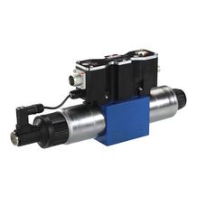

4/3 proportional directional valves with integrated digital electronics and field bus interface (IFB-P) 4WREF
-
Size 6, 10
-
Component series 2X
-
Maximum operating pressure 315 bar
-
Maximum flow 180 l/min
|
Type |
4WREF | |||
|
Size |
6 | 10 | ||
|
Installation position |
any, preferably horizontal | |||
|
Ambient temperature range |
°C |
-20 … +50 | ||
|
Storage temperature range |
°C |
-20 … +80 | ||
|
Weight |
without sandwich plate |
kg |
2.4 | 6.5 |
|
Climate |
Environmental audit according to EN 60068-2 | |||
|
MTTFd values according to EN ISO 13849 |
y |
150 | ||
|
Size |
6 | 10 | |||
|
Maximum operating pressure |
bar |
315 | |||
|
Maximum operating pressure |
Port P |
bar |
315 | ||
|
Port T |
bar |
210 | |||
|
Port A |
bar |
315 | |||
|
Port B |
bar |
315 | |||
|
Maximum flow |
l/min |
80 | 180 | ||
|
Nominal flow |
l/min |
8 16 32 |
25 50 75 |
||
|
Hydraulic fluid |
see table | ||||
|
Hydraulic fluid temperature range |
°C |
-20 … +70 | |||
|
preferably |
°C |
+40 … +50 | |||
|
Viscosity range |
mm²/s |
20 … 380 | |||
|
preferably |
mm²/s |
30 … 46 | |||
|
Maximum admissible degree of contamination of the hydraulic fluid, cleanliness class according to ISO 4406 (c) 1) |
Class 20/18/15 according to ISO 4406 (c) | ||||
|
Hysteresis 2) |
% |
≤ 0.1 | |||
|
Range of inversion 2) |
% |
≤ 0.05 | |||
|
Response sensitivity 2) |
% |
≤ 0.05 | |||
|
Zero shift upon change of: |
Hydraulic fluid temperature |
%/10 K |
< 0.15 | ||
|
Operating pressure |
%/100 bar |
< 0.1 | |||
| 1) | The cleanliness classes specified for the components must be adhered to in hydraulic systems. Effective filtration prevents faults and simultaneously increases the life cycle of the components. For the selection of the filters, see www.boschrexroth.com/filter. |
| 2) | Position control – valve control spool |
|
Hydraulic fluid |
Classification |
Suitable sealing materials |
Standards |
|
Mineral oils and related hydrocarbons |
HL, HLP |
NBR / FKM |
DIN 51524 |
|
Important information on hydraulic fluids: For more information and data on the use of other hydraulic fluids please contact us. There may be limitations regarding the technical valve data (temperature, pressure range, life cycle, maintenance intervals, etc.). The flash point of the process and operating medium used must be 40 K over the maximum solenoid surface temperature. |
|||
|
Size |
6 | 10 | ||
|
Voltage type |
Direct voltage | |||
|
Maximum current consumption |
of the amplifier |
A |
2 | |
|
of the amplifier (impulse current) |
A |
3 | ||
|
Actuated time 1) |
% |
100 | ||
|
Maximum coil temperature 2) |
°C |
150 | ||
|
Protection class according to DIN EN 60529 |
IP65 with plug-in connectors mounted and locked | |||
|
EMC (electro-magnetic compatibility) |
Interference resistance prEN 50082-2: 1994; interference emission EN 50081-1: 1992 | |||
|
Converter resolution (command/actual value signals) |
Bit |
10 | ||
|
Power supply |
V |
24 | ||
|
Supply voltage range |
V |
19,4 … 35 | ||
|
Earthing (GND) |
V |
0 | ||
|
Command value input |
"A1" |
V |
± 10 | |
|
Command value input range |
"F1" |
mA |
4 … 20 | |
|
Actual value output |
"A1" |
V |
± 10 | |
|
Actual value output range |
"F1" |
mA |
4 … 20 | |
| 1) | Connect the valve to the supply voltage only when this is required for the functional sequence of the machine. |
| 2) | Due to the surface temperatures occurring at solenoid coils, the European standards ISO 13732-1 and EN ISO 4413 need to be adhered to! |