


Бренды
Valve amplifiers for proportional pressure valves VT-VSPA1(K)-1-1X
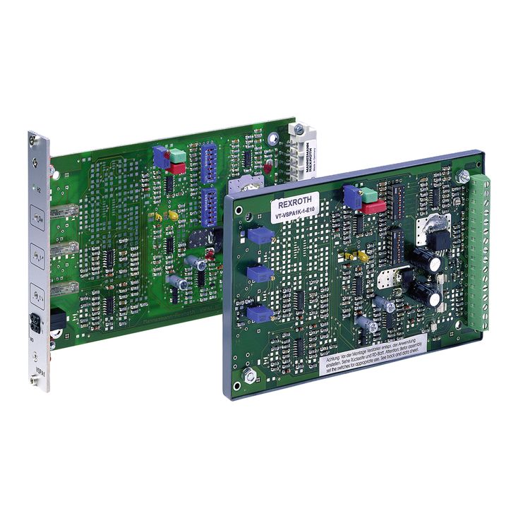

Valve amplifiers for proportional pressure valves VT-VSPA1(K)-1-1X
-
Component series 1X
-
Analog, Euro-card format
-
For valves:
DBEP 6(A/B) ...1X,
DBE(M) 10 ...5X, DBE(M) 20 ...5X, DBE(M) 30 ...3X,
(Z)DBE 6...1X,
DRE(M) 10 ...5X, DRE(M) 25 ...5X,
DRE(M) 32 ...4X,
ZDRE 10 VP ...1X
DBEP 6(A/B) ...1X,
DBE(M) 10 ...5X, DBE(M) 20 ...5X, DBE(M) 30 ...3X,
(Z)DBE 6...1X,
DRE(M) 10 ...5X, DRE(M) 25 ...5X,
DRE(M) 32 ...4X,
ZDRE 10 VP ...1X
- Differential input, switchable from voltage to current input
- Additional non-isolated command value input
- Ramp generator, separately adjustable for upwards and downwards direction
- Cable break detection for current input 4 to 20 mA
- Reverse polarity protection for the operating voltage
- Short-circuit protection and cable break detection of the solenoid conductor
- "Ready for operation" message
- Clocked power output stage
|
Type / version |
VT-VSPA1K-1-1X | VT-VSPA1-1-1X | ||
|
Type of electronics |
Analog | |||
|
Design |
Euro-card | |||
[ ] … Assignment to the block diagram
The ramp generator [4] output signal is forwarded to the summing amplifier [5] as current command value. Here, a voltage of +6 V corresponds to a command value of 100 %.
In the summing amplifier [5], the output signals of the characteristic curve generators [6 or 7] are added to the command value (can be selected by means of DIL switches depending on the valve to be controlled). The current command value can be filtered by means of a connectible low pass. The current output stage [9] is controlled using the current controller [8]. In the current controller, the current command value is moreover modulated with the clock generator signal [10] (frequency can be programmed using the DIL switch). In the valve solenoid, the clocked actual current value acts like a constant current with superimposed dither signal. Type VT-VSPA1-1 has measuring sockets for the internal command value and the actual value.
The following is true for the command value:+6 V ≙ 100 %
The following is true for the actual value: 1 mV ≙ 1 mA
The “ready for operation” signal is output and the “H2” LED on the front plate (with VSPA1-1) or the “H2” LED (with VSPA1K-1) is illuminated if:
there is no short-circuit of the solenoid conductors and no overload of the output stage,
a command value is available (cable break detection),
there is no cable break of the solenoid conductor.
In case of a fault, the following applies:
The command value input 2 is a differential input [1] (0 to +10 V). By means of DIL switches , it can be configured as current input (4 to 20 mA or 0 to 20 mA). If the command value is specified by external electronics with a different reference potential (e. g. by a PLC), this input has to be used. When disconnecting or connecting the command value voltage, it has to be ensured that both signal lines are in each case separated from or connected with the input.
Before they are forwarded, both command values are summed up [2] and then reach a potentiometer [3] accessible at the front plate of the card which acts as attenuator and thus limits the maximum command value.
The downstream ramp generator [4] generates a ramp-shaped output signal from a given stepped input signal. The time constant of this signal can be separately adjusted for the upwards and downwards direction by means of two potentiometers. The specified ramp time refers to a command value step of 100 % and may be approx. 1 s or 5 s, depending on the setting by means of a DIL switch. If a command value step of less than 100 % is switched to the ramp generator input or if the attenuator [3] is effective, the ramp time will be correspondingly shorter.
To type VT-VSPA1-1, the following applies: By means of the external “Ramp Up/Down off” contacts, the upwards and downwards ramp times can be separately set to their minimum value (approx. 30 ms).
To type VT-VSPA1K-1, the following applies: By means of the external “Ramp off” contact, the upwards and downwards ramp times can be set to their minimum value (approx. 30 ms) together.
Notice:
If an external command value potentiometer is used, the internal potentiometer “Gw” [3] must be set to maximum or to the desired maximum pressure.
The command value voltage is specified at the command value input 1 either directly or via an external command value potentiometer by means of the regulated voltage +9 V of the power supply unit [14]. The reference potential for command value 1 is M0 (measurement zero). To this input, the following applies: +9 V ≙ +100 %.
Differential input (input 2)

Internal command value presetting

External command value presetting

Ramp “up/down” off
VT-VSPA1-1

Ramp off
VT-VSPA1K-1

|
Outlet |
LED |
|
|
Short-circuit |
low |
off |
|
Cable break |
clocked |
flashing |