


Бренды
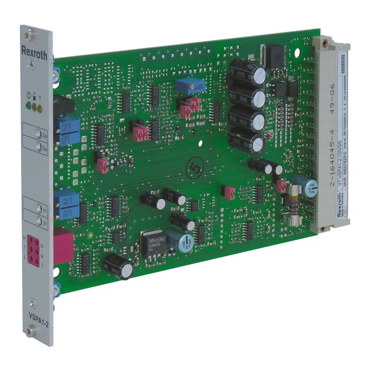
Valve amplifiers for proportional pressure valves VT-VSPA1-2

Valve amplifiers for proportional pressure valves VT-VSPA1-2
-
Component series 1X
-
Analog, Euro-card format
-
For valves:
DBET-6X, DBEM...7X
DBET-6X, DBEM...7X
- Differential inputs for voltage and current
- Ramp generator, separately adjustable for upwards and downwards direction
- External ramp time presetting
- Reverse polarity protection for the operating voltage
- Short-circuit protection and cable break detection of the solenoid conductor
- "Ready for operation" message
- Clocked power output stage
|
Type / version |
VT-VSPA1-2-1X-0 | VT-VSPA1-2-1X-A4 | ||
|
Type of electronics |
Analog | |||
|
Design |
Euro-card |
|||
Via the "frequency" potentiometer, the frequency can be corrected by >±10 % (J6 and J7 closed).
Power output stage [15]
The power output stage creates a clocked solenoid current for the proportional valve.
The output stage output is de-energized in case of an internal fault signal or if the enable is missing. The output stage output is short-circuit-proof.
Actual value output [16]
1 mA (Isolenoid) ≙ 1 mV (actual value output)
Fault recognition [17]
The solenoid conductor is monitored for cable break and short-circuits. If there is no fault, a voltage >16 V is output at the “ready for operation” output and the “ready for operation” LED is illuminated.
In case of a fault, the following applies:
Characteristic curve generator [11]
Using the potentiometer "Gw" [12], the maximum current for the solenoid is set. In the characteristic curve generator [11], the command value signal is changed so that a linear command value pressure characteristic curve (correction characteristic curve for DBET-6X and DBEM...-7X) results. For this purpose, jumper J4 has to be closed and jumper J5 has to be opened.
In order to deactivate the correction characteristic curve, jumper J4 has to be opened and jumper 5 has to be closed.
Amplitude limiter [12]
The internal command value is limited to approx. +120 % of the nominal range
Command value output [13]
0 % ≙ 0 V
+100 % ≙ +10 V
Clock generator [14]
In the clock generator [14], a frequency for the output stage is generated. The frequency is influenced by the supply voltage.
A frequency dependent on the command value signal is generated using the jumper J6 (for DBET-6X and DBEM...-7X). For a universal use, jumper J6 is to be opened.
A frequency adjustment via the "frequency" potentiometer can be realized by means of jumper J7.
Example 1:
(Frequency adjustment via "frequency" potentiometer – without command value dependency; J6 = open, J7 = closed)
Setting range: 210 Hz ... 310 Hz ±15 %
Example 2:
External ramp time setting [10]
Using an external potentiometer or external voltage presetting (according to the formula in the "Ramp generator” section), the internally set ramp time can be extended. The setting can be verified at the measuring sockets. In case of a cable break, the internal default setting will be valid automatically.
The following applies to the external potentiometer:
Formula to calculate the ramp times:
; t in ms, U in Volt at the measuring socket
Ramp on/off [9]
Using jumper J2 or the “ramp on/off” input [9] (see terminal assignment), the ramp time is set to a minimum (<50 ms).
An activated ramp is displayed by an LED.
There is no switch-over between current and voltage input. The inputs are permanently available (see block diagram).
Command value call-ups [4] (only with option A4)
Four command value call-ups "w1" to "w4" can be called up. The external voltages (command value 1 to 4) are either defined directly by the voltage output +10 V or by external potentiometers. If these command value inputs are directly connected to the regulated voltage, the command values are set at the potentiometers "w1" to "w4". When using external potentiometers, the internal potentiometers will function as attenuators or limiters.
Only one call-up can be operated at the same time. If several call-ups are operated simultaneously, call-up "w1" has the lowest priority and call-up "w4" has the highest priority. The respective active call-up is indicated via a yellow LED.
Enable function [7]
The enable function [7] enables the power output stage and forwards the internal command value signal to the ramp generator [8]. The enable signal is displayed by an LED. If the enable is connected (via 24 V input or jumper J1), the internal command value is changed (with any kind of command value presetting) by the set ramp time. Thus, a controlled valve does not open abruptly.
Ramp generator [8]
The ramp generator [8] limits the incline of the control output. The downstream amplitude limiter [12] does not extend or shorten the ramp time. Using the jumper J3, the ramp time is changed by the factor 10.
The following applies:
Power supply unit [1]
The amplifier is equipped with a power supply unit with making current limiter. This unit supplies all internally required positive and negative supply voltages.
Command value presetting [2], [3], [4], [5], [6]
The internal command value signal is calculated from the total [6] of the external command value signal or the called-up signal [4] (only with option A4) available at the differential input [2] or at the current input [3] and the zero point offset [5] (zero point potentiometer "Zw").
The following applies:

|
J3 |
Usocket/V |
2 |
1 |
0.2 |
0.1 |
0.02 |
|
open (default setting) |
t/ms |
50 |
100 |
500 |
1000 |
5000 |
|
closed |
t/s |
0.5 |
1 |
5 |
10 |
50 |
|
Outlet |
LED |
|
|
Short-circuit |
low |
off |
|
Cable break |
clocked |
flashing |
|
Setting range |
||
|
R |
min. ramp time (potentiometer at left turn) |
max. ramp time (rotary angle of the potentiometer at approx. 95%) |
|
1 kΩ |
100 ms |
1 s |
|
100 Ω |
1 s |
10 s |
|
The minimum ramp time can only be reached if the internally set ramp time is lower, i.e. the corresponding potentiometer is at the left turn. The specified ramp times are true for J3 = open. |
||
|
“Ramp on/off” input |
J2 |
LED "T" |
Ramp |
|
0 V |
open |
on |
on |
|
24 V |
open |
off |
off |
|
0 V |
closed |
off |
off |
|
24 V |
closed |
on |
on |
|
Standard values |
Current input |
Differential input |
Command value socket |
|
0 % |
4 mA |
0 V |
0 V |
|
+100 % |
20 mA |
+10 V |
+10 V |