


Бренды
Valve amplifiers for proportional directional valves and proportional pressure valves VT-VSPA2-1-2X
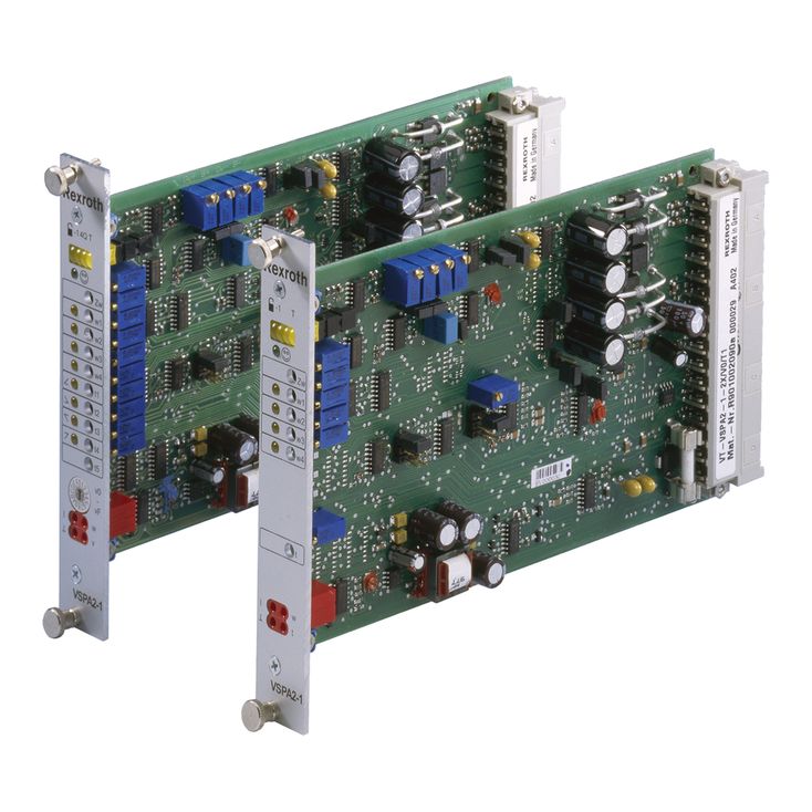

Valve amplifiers for proportional directional valves and proportional pressure valves VT-VSPA2-1-2X
-
Component series 2X
-
Analog, Euro-card format
-
For valves:
4WRA...-2X
4WRZ...-7X
3DREP6...-2X
4WRA...-2X
4WRZ...-7X
3DREP6...-2X
- Differential inputs for voltage and current
- Four callable command value inputs, input for ramp time
- Digital inputs for enable, ramp, inverting and command value call-up
- Model T5 with 5 ramps and quadrant recognition
- Adjustable ramp times, step level and maximum solenoid current
- Reverse polarity protection for the operating voltage
- Switchable measuring socket with version T5
- "Ready for operation" output
- Power supply unit with DC/DC converter without raised zero point
|
Type / version |
VT-VSPA2-1-2X-T1 | VT-VSPA2-1-2X-T5 | ||
|
Type of electronics |
Analog | |||
|
Design |
Euro-card | |||
By closing the jumper J3, the ramp times specified above can be increased tenfold.
Characteristic curve generator [10]
Using the adjustable characteristic curve generator, step level and maximum values for positive and negative signals can be set separately based on the hydraulic requirements. The actual development of the characteristic curve through the zero point is not stepped but linear.
Amplitude limiter [11]
The internal command value is limited to approx. ±110 % of the nominal range.
Clock generator [13]
The clock generator creates the clock frequency of the output stages. The clock signal can be switched in three basic frequency ranges using jumpers.
Power output stage [16]
The power output stage generates the clocked solenoid current for the proportional valve. The solenoid current is limited to 2.5 A per output. The output stage outputs are short-circuit-proof. The output stages are de-energized in case of an internal fault signal or if the enable is missing.
Fault recognition [17]
Monitors over-current of the output stage.
[ ] = Assignment to the block diagrams
There is no switch-over between current and voltage input. The inputs are permanently available (see block diagram).
Command value call-ups [4]
Four command value signals "w1" to "w4" can be called up. The external command value voltages (command value 1 to 4) are either defined directly by the regulated voltage outputs +10 V and –10 V or by external potentiometers. If these command value inputs are directly connected to the regulated voltages, the command values are set at the potentiometers "w1" to "w4". When using external potentiometers, the internal potentiometers will function as attenuators or limiters.
Only one call-up can be operated simultaneously. If several call-ups are operated simultaneously, call-up 1 has the lowest priority and call-up 4 has the highest priority.
The respective active call-up is indicated by a yellow LED on the front plate.
Command value inverting [7]
The command value created internally from the input signals, the command value call-ups and the zero point offset signal can be inverted by an external signal or by jumper J1. The inverting is displayed by an LED "–1" on the front plate.
Enable function [8]
The enable function enables the power output stages and forwards the internal command value signal to the ramp generator. The enable signal is indicated by an LED on the front plate. If enable is connected, the internal command value is changed (with any kind of command value presetting) by the set ramp time. Thus, a controlled valve does not open abruptly.
Ramp generator [9]
The ramp generator limits the incline of the control output. The downstream step functions and amplitude attenuators do not extend or shorten the ramp time.
Using a “ramp on/off” signal or jumper J2, the ramp time is set to a minimum (< 2 ms) (ramp off).
External ramp time setting:
Using an external potentiometer the internally set ramp time can be extended. The setting can be verified by means of the measuring socket. In case of a cable break, the internal default setting will be valid automatically.
Table for setting and measurement of the ramp time:
Power supply unit [1]
The amplifier card has a power supply unit with making current limiter. This unit supplies all internally required positive and negative supply voltages.
Command value presetting
The internal command value signal is calculated from the total (summation [6]) of the external command value signal available at the differential input [2] and at the current input [3], the called-up signal [4] and the zero point offset [5] (zero point potentiometer "Zw").
The following applies:
|
Value at measuring socket |
U/V |
5 |
3 |
2 |
1 |
0.5 |
0.3 |
0.2 |
0.1 |
0.05 |
0.03 |
0.02 |
|
Current ramp time (±20 %) |
t/ms |
20 |
33 |
50 |
100 |
200 |
333 |
500 |
1000 |
2000 |
3333 |
5000 |
|
Standard values |
Current input |
Differential input |
Command value socket |
Solenoid |
|
-100 % |
4 mA |
-10 V |
-10 V |
a |
|
0 % |
12 mA |
0 V |
0 V |
|
|
+100 % |
20 mA |
+10 V |
+10 V |
b |
|
If the current input is not wired-up or if the cable of the current command value is broken, the resulting internal command value signal is 0%. |
||||