


Бренды
Valve amplifiers for proportional pressure valves VT 2000-5X
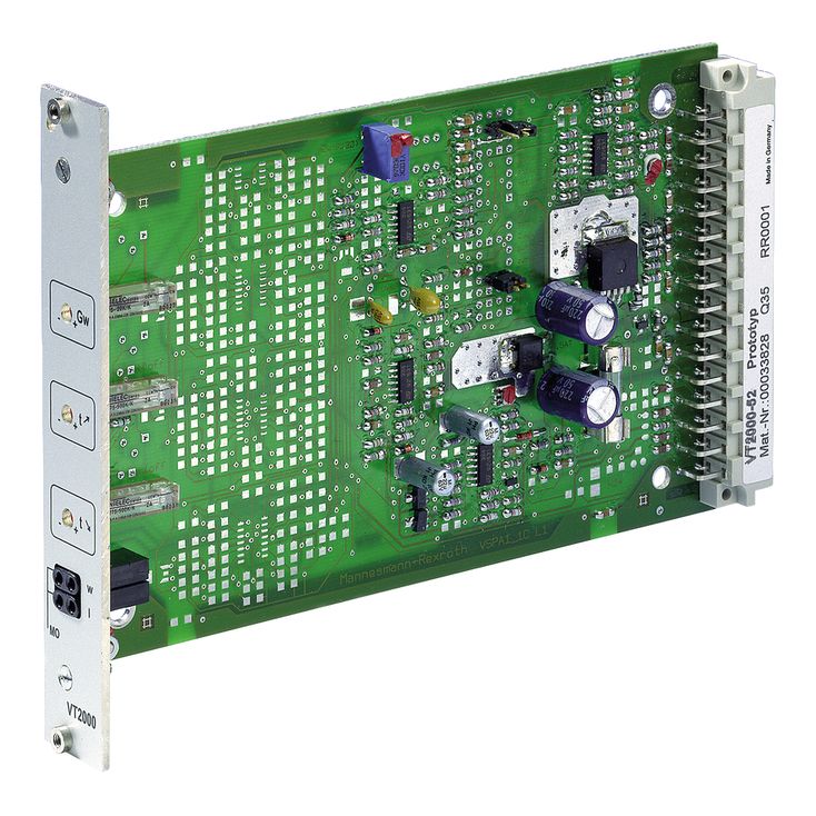

Valve amplifiers for proportional pressure valves VT 2000-5X
-
Component series 5X
-
Analog, Euro-card format
-
For valves: Proportional pressure control valves
- Differential input
- Additional non-isolated command value input
- Ramp generator, separately adjustable for upwards and downwards direction
- Reverse polarity protection for the operating voltage
- Short-circuit protection of the solenoid conductor
- Clocked power output stage
|
Type of electronics |
Analog | ||
|
Design |
Euro-card |
The output signal of the ramp generator [4] is the internal current command value and is supplied to the measuring socket “w” on the front plate of the card. Here, a voltage of +6 V corresponds to a command value of 100 %. In addition, the command value is supplied to the current output stage [6] by the current controller [5]. In the current controller [5], the value of potentiometer “Zw” (R130) for the pilot current is added to the value from the ramp generator. The current command value is modulated by the clock generator signal [7]. In the valve solenoid, the clocked actual current value acts like a constant current with superimposed dither signal. The actual current value through the solenoid can be measured at socket “I”. Here, a current of 800 mV corresponds to a voltage of 800 mA.
[ ] … Assignment to the block diagram
The command value input 2 is a differential input [1] (0 to +10 V). If the command value is specified by external electronics with a different reference potential (e. g. by a PLC), this input has to be used. When disconnecting or connecting the command value voltage, it has to be ensured that both signal lines are in each case separated from or connected with the input.
Before they are forwarded, both command values are summed up [2] and then reach a potentiometer [3] accessible at the front plate of the card which acts as attenuator and thus limits the maximum command value.
The downstream ramp generator [4] generates a ramp-shaped output signal from a given stepped input signal. The time constant of this signal can be separately adjusted for the upwards and downwards direction by means of two potentiometers. The specified ramp time refers to a command value step of 100 % and may be approx. 1 s or 5 s depending on the jumper adjustment. If a command value step of less than 100 % is switched to the ramp generator input or if the attenuator [3] is effective, the ramp time will be correspondingly shorter.
By means of the external “ramp up/down off” contacts, the upwards and downwards ramp times can be separately set to their minimum value (approx. 30 ms).
Notice:
If an external command value potentiometer is used, the internal potentiometer “Gw” [3] must be set to maximum or to the desired maximum pressure.
The command value voltage is specified at the command value input 1 either directly or via an external command value potentiometer by means of the regulated voltage +9 V of the power supply unit [8]. The reference potential for command value 1 is M0 (measurement zero). To this input, the following applies: +9 V ≙ +100 %.
External command value presetting

Differential input (input 2)


Internal command value presetting
