


Бренды
Valve amplifiers for servo-valves VT-SR2-1X
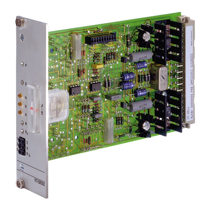

Valve amplifiers for servo-valves VT-SR2-1X
-
Component series 1X
-
Analog, Euro-card format
-
For valves: 4WS2EM 6-2X, 4WS2EM 10-5X and 4WS2EM 16-2X
- Voltage input
- Controller for valve flow
- Enable input
- Output stage with dither signal
- Measuring instrument for valve flow display
- Reverse polarity protection for the operating voltage
|
Type / version |
VT-SR2-…/...-60 | VT-SR2-…/...-100 | |
|
Component series |
1X | ||
|
Type of electronics |
Analog | ||
|
Design |
Euro-card | ||
The valve amplifiers operate with a push-pull output stage with bipolar transistors. The output of this output stage can be connected or disconnected by means of an enable circuit (relay K2). The enable is indicated by the LED "H2" on the front plate being illuminated. The switching voltage of all relays is defined by means of jumpers J12 and J13 to either 0 V or +UB (factory +UB).
The output stage consists of an I controller with connected dither signal generator. The amplitude of the dither signal is set by means of R7. The pre-stage (current command value) is controlled via a PD controller. The actual current value returned is simultaneously indicated by the instrument on the front plate.
The PD controller is supplied the position command value with the D share only affecting input 3.
The zero point can be set via R3 (NP) from the front plate.
The required symmetric operating voltage +UB is protected against reversed polarity. The design without voltage regulator requires an additional stable auxiliary voltage (±UM) to supply the controller electronics. The auxiliary voltage port is protected against reversed polarity up to a maximum current of 1 A.
As an option, the amplifier can be equipped with a PID controller (D share only affects the actual value) with a switchable PI share and a backup relay with potential-free changeover contact. This controller can be used to superimpose a further control loop (e.g. for drive control). The P and D share can be set at the front plate. The controller switching status is indicated by the LED "H1", the relay at LED "H3" (LEDs illuminated if relays are applied). The PID controller fitting is customer-specific and therefore has to be specified in the order in plain text. These amplifiers receive a special type designation upon delivery. The backup relay is loadable up to 28 V and 2 A.