


Бренды
Duplex filter with filter element acc. to DIN 24550 150 LD(N)

Duplex filter with filter element acc. to DIN 24550 150 LD(N)
-
Size 0040 … 0400
-
Max. operating pressure 160 bar
-
Flow, max. 135 l/min
-
Operating temperature -10 … +100 °C
- Filters for inline installation
- Special highly efficient filter media
- Filtration of very fine particles and high dirt holding capacity across a broad pressure differential range
- High collapse resistance of the filter elements
- Standard version equipped with mechanical/visual maintenance indicator with memory function
- Optional equipment with various electrical switching elements, modular design
- Optional bypass valve integrated in the filter housing
- Druckausgleichsfunktion in Umschaltung integriert
- Optional measuring port
|
Size |
0040 | 0063 | 0100 | 0130 | 0150 | 0160 | 0250 | 0400 | ||
|
Weight |
7.4 kg | 8.5 kg | 10.3 g | 13.9 kg | 17.3 kg | 21.6 kg | 23.4 g | 26.2 kg | ||
|
Volume |
2x0,35 l | 2x0,45 l | 2x0,7 l | 2x0,82 l | 2x0,98 l | 2x1,25 l | 2x1,95 l | 2x2,9 l | ||
|
Installation position |
Vertical | |||||||||
|
Material |
Filter head |
GGG | ||||||||
|
Filter bowl |
Steel | |||||||||
|
Bypass valve |
Aluminum / steel / POM | |||||||||
|
Seals |
NBR / FKM | |||||||||
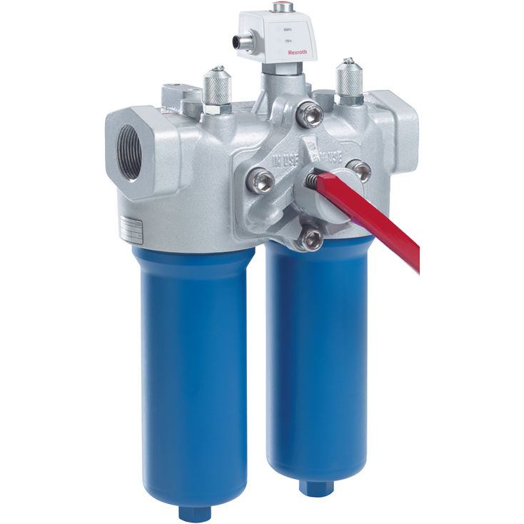
The 150LD(N) duplex filter is suitable for direct installation into pressure lines. It is installed upstream of components to be protected. Any use in the suction area is not admissible.
It basically consists of a filter head (1) with switch-over fitting (6) and integrated pressure equalization function, two screwable filter bowls (2), two filter elements (3) as well as a mechanical optical maintenance indicator (4).
In case of filters with low-collapse filter elements (= code letter pressure differential A), there is also an integrated bypass valve (11).
Via the inlet, the fluid reaches the filter element (3) where it is cleaned. The dirt particles filtered out collect in the filter element (3). Via the outlet, the filtered fluid enters the hydraulic circuit.
The filter housing and all connection elements are designed so that pressure peaks ‒ as they may e.g. occur in case of abrupt opening of large control valves due to the accelerated fluid quantity ‒ can be securely absorbed.
For sizes 0160 and larger, the filter bowl is equipped with a drain plug (7).
Via the bleed screws and/or the optional bleed valves ‒ amending information E ‒ (8, 9), the filter side to be maintained can be bled.
Measuring ports in the form of threaded couplings on clean and dirt side are available in the type key under the amending information "M".
Only then will the filter head be drilled accordingly.
By default, the filter is equipped with mechanical optical maintenance indicator (4). The electronic switching element (10) which has to be ordered separately is attached to the mechanical optical maintenance indicator (4) and held by means of a locking ring.
The electronic switching elements with 1 or 2 switching points are connected via a mating connector according to IEC-60947-5-2 or via a cable connection according to EN17301-803.
Notice: