


Бренды
Filter element 73.

Filter element 73.
-
Size 0110 … 0270
-
Maximum collapse pressure rating 210 bar 30 bar
-
Filter rating 3 µm
-
Filter area 4.8 cm²
-
Operating temperature range -10 … +100 °C
- Special highly efficient filter media
- Hohe Schmutzaufnahme und Filtrationsleistung durch mehrlagige Glasfasertechnik bei gleichzeitig niedrigem Anfangsdifferenzdruck (ISO 3968)
- Low initial pressure differential (ISO 3968)
- Funktionsfilterelement mit zwei Filtrationsstufen für die Windkraft
|
Type |
73. | 73. | 73. | 73. | 73. | 73. | |||
|
Size |
0110 | 0120 | 0135 | 0145 | 0200 | 0270 | |||
|
Weight |
m |
1.9 kg | 3.3 kg | 3.7 kg | 4.3 kg | 6 kg | |||
|
nominal filter rating |
3 µm | ||||||||
|
Filter area |
4.8 cm² | ||||||||
|
Ambient temperature range |
-40 … +50 °C | ||||||||
|
Operating temperature range |
-10 … +100 °C | ||||||||
|
Material |
Filter element |
Tin-coated steel | |||||||
|
Filter element |
Aluminium | ||||||||
|
Filter element |
Tin-coated steel | ||||||||
|
|
bNBR | ||||||||
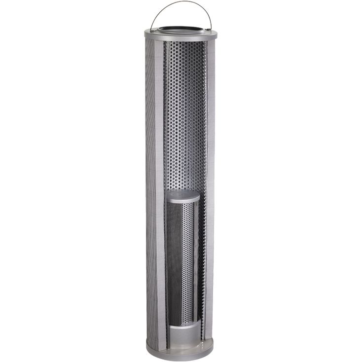
The filter element is the central component of a filter assembly. The actual filtration process takes place in the filter element. The main filter variables, such as retention capacity, dirt holding capacity and pressure loss are determined by the filter elements and the filter media used in them.
These Rexroth Filter elements are used to filter lubricants in wind turbines. The series 73. filter elements consist of two separate filter elements which are designed in series so fluid flows through one filter followed by the second filter.
In order to achieve the cleanliness class, the outer filter element (1) made of glass fiber media serves as the main filter. The inner filter element (2) made of wire mesh serves as a protective filter in case of a cold start. The outer filter element consists of a multi-layer combination of star-like pleated filter media which are laid around a perforated supporting tube. The inner filter element has the same general design, except the filter material is different.
The bypass valve (3) (see schematic) is located in the filter head of the filter housing.
Possible operating conditions:
1. Normal operation with a clean fi lter element:
The fluid flows through the outer filter element (1). The bypass valve is closed. When the fluid flows to the filter outlet, it passes the inner filter element (2).
2. Cold start or highly contaminated outer filter element:
A very small portion of the fluid flows through the outer filter element (1). Nearly all of the fluid passes through the bypass valve, which is completely open. Through the open bypass valve (3), dirt particles get to the clean side of the outer filter element (1). But the inner filter element (2) still retains any coarse particles. Therefore, the downstream components are still protected, even under these bypass conditions.