


Бренды
Pressure differential indicators for filters in pressure lines WO-D01
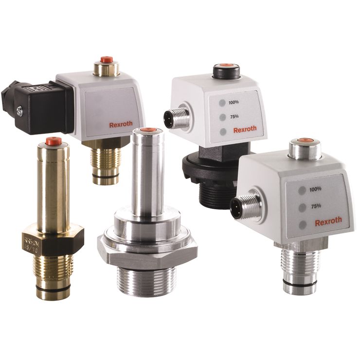

Pressure differential indicators for filters in pressure lines WO-D01
-
Max. operating pressure 450 bar
-
Operating temperature -30 … +100 °C
- Modular structure
- Mechanical/visual indicators WO with one switching point and memory function
|
Type / version |
WO-D01-0,8-M-160 | WO-D01-0,8-V-160 | WO-D01-1,5-M-160 | WO-D01-1,5-V-160 | WO-D01-2,2-M-160 | WO-D01-2,2-V-160 | WO-D01-2,2-M-450 | WO-D01-2,2-V-450 | WO-D01-5,0-M-450 | WO-D01-5,0-V-450 | WO-D01-8,0-M-450 | WO-D01-8,0-V-450 | ||
|
Type / version |
WO-D01-0, 8-M-160 |
WO-D01-0, 8-V-160 |
WO-D01-1, 5-M-160 |
WO-D01-1, 5-V-160 |
WO-D01-2, 2-M-160 |
WO-D01-2, 2-V-160 |
WO-D01-2, 2-M-450 |
WO-D01-2, 2-V-450 |
WO-D01-5, 0-M-450 |
WO-D01-5, 0-V-450 |
WO-D01-8, 0-M-450 |
WO-D01-8, 0-V-450 |
|||
|
Type of pressure measurement |
Pressure differential | ||||||||||||||
|
Operating pressure |
max. |
pmax |
bar |
160 | 450 | ||||||||||
|
Switching pressure |
bar |
0.8 | 1.5 | 2.2 | 5 | 8 | |||||||||
|
Switching pressure tolerance |
bar |
± 0.15 | ± 0.2 | ± 0.3 | ± 0.5 | ± 0.8 | |||||||||
|
Operating temperature range |
°C |
-30 … +100 | |||||||||||||
|
Material |
Aluminium | Brass | |||||||||||||
|
Material |
Seals |
NBR | FKM | NBR | FKM | NBR | FKM | NBR | FKM | NBR | FKM | NBR | FKM | ||
|
Tightening torque |
max. |
MA max |
Nm |
50 | |||||||||||
By default, the Rexroth filters are supplied with a mechanical/visual maintenance indicator (WO). The electronic switching element (WE) is available as accessory and compatible with all mechanical/visual maintenance indicators. The electronic switching element is attached to the visual maintenance indicator and fixed by means of a locking ring. The electronic maintenance indicator is not dependent on the nominal pressure of the filter.
The increasing back pressure and/or pressure differential pushes a piston (1) against a spring (2) upwards. The solenoid (3) mounted on the piston is moved together with the piston. The visual pin (4) may take two valid positions. If the position of the piston (1) with solenoid (3) is below the nominal pressure of the maintenance indicator, the visual pin remains in retracted “rest position”. Upon first exceedance of the nominal pressure, the position of the visual pin (5) is changed rapidly into the second possible “On condition” by repellence of the solenoid of the pin (5) to the solenoid of the piston (3). The pin will permanently remain in this extended position, even visible after machine switch-off (or pressure drop, cold start) (memory function). It has to be acknowledged.