


Бренды
Modular plate systems IH20

Modular plate systems IH20
-
Component series 1X
-
Maximum operating pressure 315 bar
-
Nominal flow 50 l/min, 200 l/min
-
Frame size A and B
- Modular block system for set-up of controls in a compact construction, ready for connection
- Different sizes of one frame size can be combined in any order
- Pressure and tank ports for all control circuits on both front sides of the mounted IH20 stacking assemblies
- Separate actuator ports A and B per control circuit
- The material number includes the respective segment with all plug screws and seals
- Functional elements such as valves or nozzles are not included
- For detailed circuit diagrams and device lists of a complete IH20 stacking assembly see the respective order documentation
|
Ambient temperature range |
NBR seals |
°C |
-30 … +50 | |
|
FKM seals |
°C |
-20 … +50 | ||
|
Installation position 1) |
any, preferably horizontal | |||
|
Surface protection |
Galvanic coating DIN 50979 - Fe//Zn8//Cn//T0 | |||
|
Material |
EN-JS1030/EN-GJS-400-15 (0.7040/GG-40) | |||
1) Observe the valve details
Function
The type IH20 control system (complete assembly) can be realized individually from different modules and additional vertical stackings. Functionality will differ according to the selected modules, valves etc.
This data sheet describes the properties of the individual modules with frame sizes A and B of the premium and standard programs which are primarily designed for direct operated or for internally pilot-operated directional valves.
Other functions (modules) in these frame sizes and modules for larger nominal volume flows (frame sizes C and D) are available on request.
The maximum volume flows possible for the individual frame sizes depend on the admissible flow velocities of the relevant application and the existing thread connections and/or connection flanges at the IH 20 modules. Actuator ports are usually located on the back.
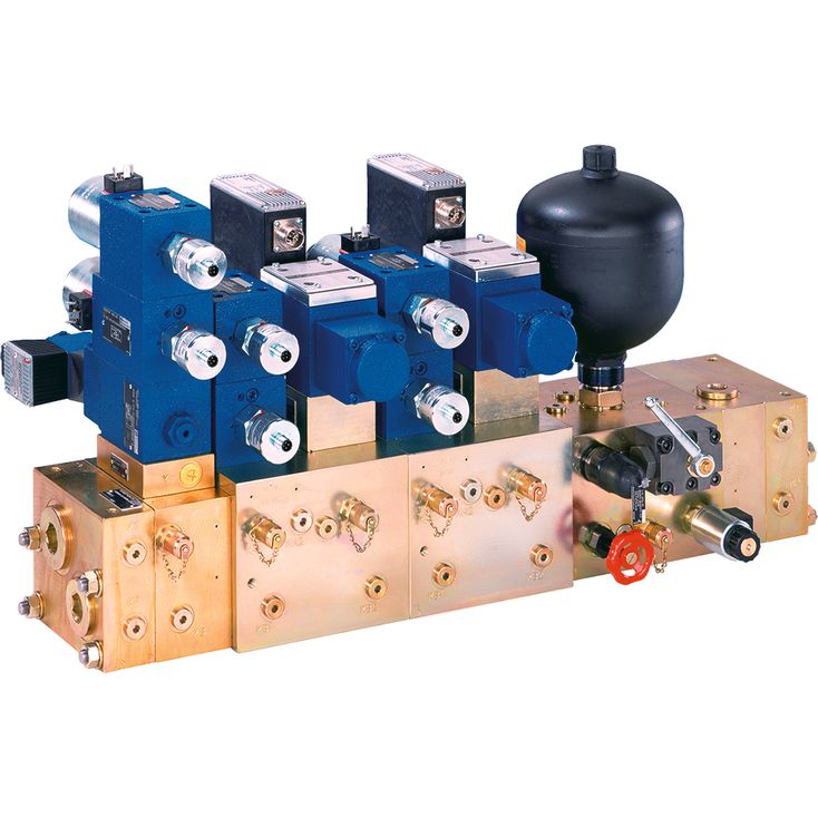
System set-up
The type IH20 control system (complete assembly) usually consists of the following elements:
▶ Inlet segment
▶ Intermediate segment(s)
▶ Sandwich plates, valves etc.

|
1 |
Inlet segment left |
|
2 |
2-way cartridge valves (logic) |
|
3 |
Accumulator segment |
|
4 |
Check function in P |
|
5 |
Valve segment |
|
6 |
Pump inlet segment |
|
7 |
Inlet segment right |
|
8 |
Threaded bolt |
