


Бренды
Pump manifold blocks PSBD02

Pump manifold blocks PSBD02
-
Size 40, 71, 180, 355
-
Component series 1X
-
Maximum operating pressure 350 bar
-
Maximum flow 600 l/min
- Contamination of maximum pressure limitation, start-up and/or circulation at zero pressure and pressure measurement
- Attachment of a pressure switch, a second pressure rating and a proportional servo valve possible
- Influencing of the pump controller
- Direct attachment to axial piston pumps A4VSO NG40 to NG355
|
Weight with maximum fitting |
|
Size |
40 | 71 | 180 | 355 |
|
|
kg |
23 | 27 | 30 | 40 | |
|
Installation position |
any | |||||
|
|
NBR seal | FKM seal | ||
|
Ambient temperature range 1) |
HED according to data sheet 50061 |
°C |
-25 … +50 | -20 … +50 |
|
WE according to data sheet 23178 |
°C |
-30 … +50 | -20 … +50 | |
|
DBET according to data sheet 29162 |
°C |
— | -20 … +70 | |
|
DBETE according to data sheet 29162 |
°C |
— | -20 … +50 | |
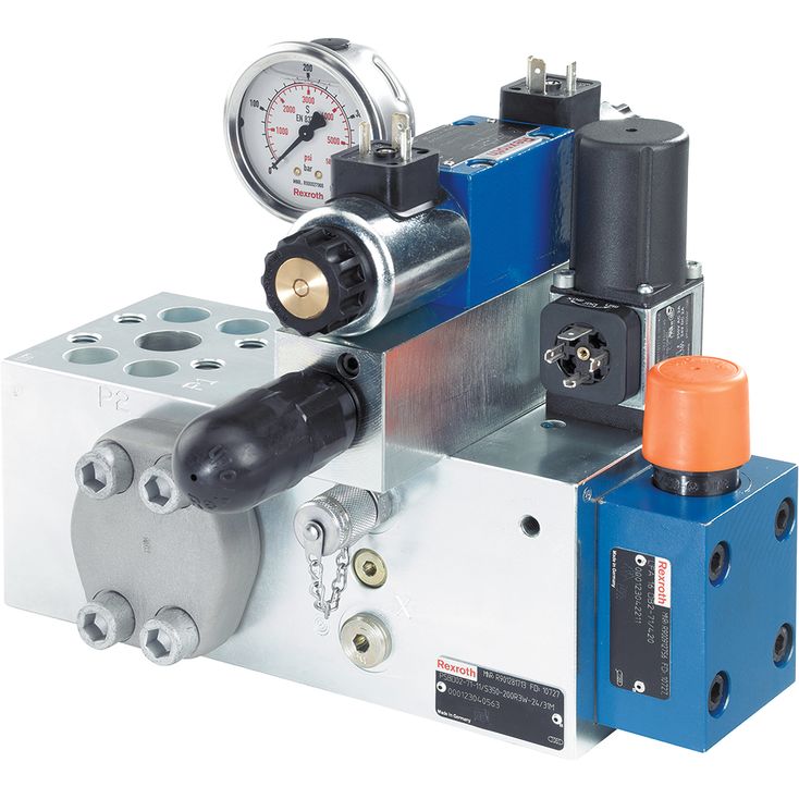
Function, exploded drawing
The pump manifold blocks basically consist of the valve block (1), the cartridge valve (2) with pilot control valve (3) (according to data sheet 21050) of the pressure relief function and the control valve (5) 4WE6… (according to data sheet 23178). Optionally, a pressure switch (8) type HED 8 (according to data sheet 50061) and a pressure gauge (6) can be attached.
At the block bottom side, the valve block has a P connection (SAE high-pressure series) for the input and a total of 3 connections (SAE high-pressure series) P1, P2 and P3 for the output of the hydraulic fluid as well as one tank port T (SAE standard pressure series).
In an internally bored branch, there is the cartridge valve (2) and the pilot control valve (3). Via the open function of the valve, there is a connection to the T port (SAE standard pressure series).
By means of orifice/plug fitting in threads "C", "D", and "E", the pump manifold block can be adjusted to different pump types and controller variants.
In the basic version, the control line of the cartridge valve (2) and the pilot control valve (3) is unloaded to the tank via the 4WE6HB… (5) control valve (cartridge valve is open, P-T connection is established). If solenoid b of the control valve (5) is connected, the control line of the cartridge valve (2) and the pilot control valve (3) is closed, the pending pressure P-P1-P2-P3 acts on the main spool of the cartridge valve (2); at the same time, the pressure is applied to the pilot control valve (3) via an auxiliary bore. If the pressure in P reaches the set pressure of the pilot control valve (3), the latter is opened. The spring chamber of the cartridge valve (2) is unloaded and due to the hydraulic state of equilibrium, hydraulic fluid flows from P, P1, P2, P3 to channel T, maintaining the set operating pressure. With controller option "F" and "G", this operating pressure must also be set at the controller-influenced pressure relief valve (4.1) of the sandwich plate (4).
Optionally, a second pressure rating can be selected electrically via the sandwich plate (4), via solenoid a of the control valve 4WE6H… (5). However, the set pressure must be less than the pressure set at the pilot control valve (3).
Representation corresponds to NG71.
The position of the valves and orifices may slightly differ for other sizes and can be seen from the relevant installation drawing.
