


Бренды
Δp/Q controller VT-VACAF-1X
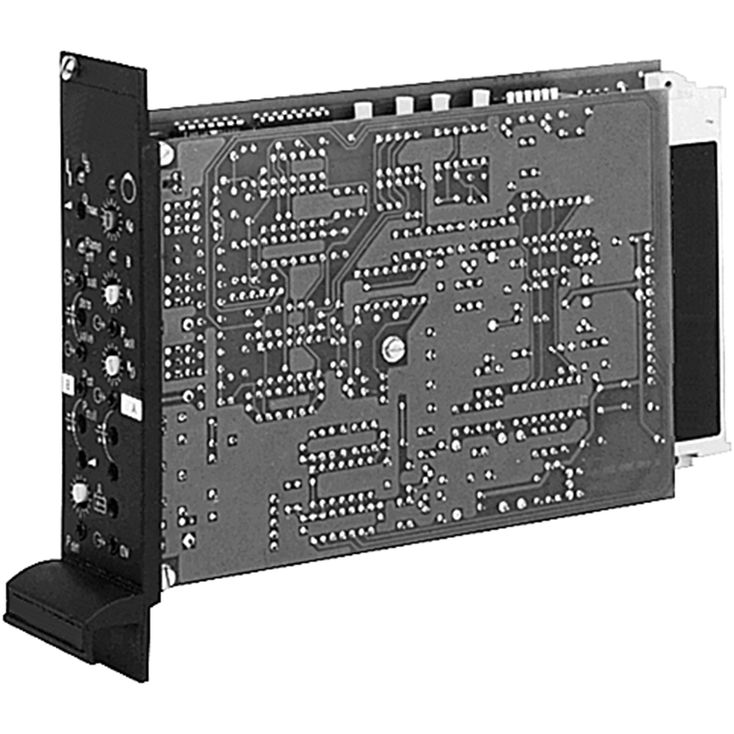

Δp/Q controller VT-VACAF-1X
-
Component series 1X
- Suitable for controlling high-response valves
- Amplifier with additional electronics (daughter card)
- Analog amplifiers in Europe format for installation in 19" racks
- Pressure differential controller (force controller) with PID behavior
- Short-circuit-proof outputs
- External shut-off for pressure controller
- External shut-off for pressure controller
- Separate acceleration and braking ramp
- Ramps can be separately adjusted and switched off
- Adjustable area adjustment for cylinder
- Suitable for pressure sensors (0...10 V, 4...20 mA), see data sheet 30271
- Supply for pressure sensors
- Cable break detection for pressure sensor
|
Supply voltage |
nominal 24 V= battery voltage 21...40 V, rectified alternating voltage Ueff = 21...28 V (single-phase, full-wave rectifier) |
|||
|
Smoothing capacitor, separately |
Recommendation: Capacitor module VT 11110 (see data sheet 30750) (only necessary if the ripple of UB >10 %) |
|||
|
Current consumption, max. |
mA |
250 | ||
|
Command value Q |
b20: 0...±10 V – differential amplifier z20: 0...±10 V – differential amplifier (Ri= 100 kΩ) |
|||
|
Command value pdiff |
z10: 0...+10 V – differential amplifier z12: 0 V – differential amplifier |
|||
|
Actual value from the pressure sensor |
A |
b26: 0...±10 V – differential amplifier b28: 0 V – differential amplifier z24: z30: 4...20 mA |
||
|
B |
b16: 0...±10 V – differential amplifier b18: 0 V – differential amplifier z14: z30: 4...20 mA |
|||
|
Pressure sensor supply |
z6: +15 V, max. 100 mA z8: -15 V, max. 100 mA |
|||
|
Pressure controller OFF |
b10: 6...40 V= | |||
|
External controller enquiry |
V= |
z24: 24 V/0.1 A max., if controller is not active | ||
|
Signal source |
Supply ±10 V from b32, z32 (10 mA) or external signal source | |||
|
Monitor signal Factual |
z16: ±10 V | |||
|
Error pressure sensor |
b22: no error: +UB; max. 100 mA error: 0 V : LED "Ramp OFF A" and "Ramp OFF B" flash |
|||
|
Ramp times |
min. 350 ms (1), max. 5.6 s (16) 16 stages, 350 ms/stage |
|||
|
Ramp OFF |
A |
z22: 8...40 V = | ||
|
B |
z26: 8...40 V = | |||
|
Area adjustment cylinder |
min. 1:1 (1), max. 1:4 (16) 16 stages |
|||
|
LED displays |
red |
Error UB | ||
|
red |
Ramp OFF A | |||
|
red |
Ramp OFF B | |||
|
green |
Controller active | |||
|
yellow |
Controller not active | |||
|
off |
Controller OFF | |||
|
Plug-in connection |
Plug to DIN 41612-F32 | |||
|
Operating temperature |
°C |
0+70 | ||
|
Storage temperature range |
°C |
-20 … +70 | ||
|
Weight |
m |
kg |
0.44 | |
Force control

|
Qcommand |
Direction |
pdiff. command |
Direction |
Track traveling |
Force control |
|
+5,0 V |
 |
+3,5 V |
|
with 50 % vmax. |
after track traveling to 35 % of pdiff. max. |
|
+7,5 V |
|
-2,0 V |
 |
with 75 % vmax. |
not possible |
|
-3,3 V |
|
-4,8 V |
|
with 33 % vmax. |
after track traveling to 48 % of pdiff. max. |
|
-10,0 V |
|
+8,0 V |
|
with vmax. |
not possible |
|
A command value of at least ±0.3 V must be specified! |
|||||
|
The numerical values listed in the table are examples, the signs of the values are decisive. |
|||||