


Бренды
Inline filter with filter element according to DIN 24550 50 LE(N)
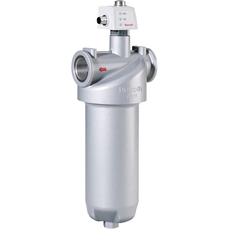

Inline filter with filter element according to DIN 24550 50 LE(N)
-
Size 0040 … 0400
-
Max. operating pressure 50 bar
-
Flow, max. 300 l/min
-
Port G 3/4, G 3/4, G 3/4, G 1, G 1, G 1 1/2, G 1 1/2, G 1 1/2
-
Operating temperature -10 … +100 °C
- Filters for inline installation
- Special highly efficient filter media
- Filtration of very fine particles and high dirt holding capacity across a broad pressure differential range
- High collapse resistance of the filter elements
- Standard version equipped with mechanical/visual maintenance indicator with memory function
- Optional equipment with various electrical switching elements, modular design
- Optional bypass valve integrated in the filter housing
|
Size |
0040 | 0063 | 0100 | 0130 | 0150 | 0160 | 0250 | 0400 | |||
|
Installation position |
Vertical | ||||||||||
|
Ambient temperature range |
ϑ |
°C |
-10 … +100 | ||||||||
|
Weight |
m |
kg |
1.05 | 1.1 | 1.2 | 1.91 | 2.06 | 3.1 | 3.3 | 3.8 | |
|
Volume |
l |
0.27 | 0.39 | 0.58 | 0.89 | 1.1 | 1.31 | 1.89 | 2.84 | ||
|
Material |
Filter head |
Aluminium | |||||||||
|
Filter bowl |
Aluminium | ||||||||||
|
Bypass valve |
Aluminum / steel / POM | ||||||||||
|
Seals |
NBR / FKM | ||||||||||
The 50LE(N) inline filter is suitable for direct installation into pressure lines. It is installed upstream components to be protected.
It basically consists of filter head (1), a screwable filter bowl (2), filter element (3) as well as mechanical/visual maintenance indicator (4). In case of filters with low-pressure-differential-stable filter elements (= code letter pressure differential A), there is an assembled bypass valve (5) by default.
The installed spring (6) prevents possible vibrations of the filter element (3). During disassembly, the contact pressure of the spring (6) holds the filter element in the filter bowl (2).
Via the inlet, the fluid reaches the filter element (3) where it is cleaned. The dirt particles filtered out settle in the filter element (3). Via the outlet, the filtered fluid enters the hydraulic circuit.
The filter housing and all connection elements are designed so that pressure peaks - as they may e.g. occur in case of abrupt opening of large control valves due to the accelerated fluid quantity - can be securely absorbed. As of size 0160, the standard equipment comprises a drain screw (7).
By default, the filter is equipped with mechanical/visual maintenance indicator (4). The electronic switching element (8) which has to be ordered separately is attached to the mechanical/visual maintenance indicator (4) and held by means of a locking ring. The electronic switching elements with 1 or 2 switching points are connected via a mating connector or via a cable connection.