


Бренды
Inline filter with filter element according to DIN 24550 350 LE(N)

Inline filter with filter element according to DIN 24550 350 LE(N)
-
Size 0063 … 1000
-
Max. operating pressure 350 bar
-
Flow, max. 650 l/min
-
Port G 1, G 1, G1 1/4, G1 1/4, G1 1/2, G1 1/2, G1 1/2, G2, G2
-
Operating temperature -10 … +100 °C
- Filters for inline installation
- Special highly efficient filter media
- Filtration of very fine particles and high dirt holding capacity across a broad pressure differential range
- High collapse resistance of the filter elements
- Standard version equipped with mechanical/visual maintenance indicator with memory function
- Optional equipment with various electrical switching elements, modular design
- Optional bypass valve integrated in the filter housing
- High filtration performance due to the tangential cyclone-effect flow path
- Erweiterte Konfiguration für Sonderfluide möglich
|
Size |
0063 | 0100 | 0130 | 0150 | 0160 | 0250 | 0400 | 0630 | 1000 | |||
|
Installation position |
vertical | |||||||||||
|
Ambient temperature range |
ϑ |
°C |
-30 … +100 | -10 … +65 | ||||||||
|
Weight |
m |
kg |
6.3 | 7 | 10.5 | 11.2 | 22.7 | 27.5 | 35.2 | 66.4 | 140.3 | |
|
Volume |
l |
0.35 | 0.52 | 0.9 | 1.1 | 1.3 | 1.9 | 3 | 4.5 | 6.5 | ||
|
Material |
Filter head |
GGG | ||||||||||
|
Filter bowl |
Steel | |||||||||||
|
Bypass valve |
Aluminum / steel / POM | |||||||||||
|
Seals |
NBR / FKM | |||||||||||
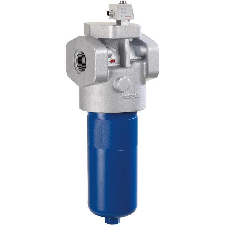
The 350LE(N) inline filter is suitable for installation into pressure lines.
It basically consists of filter head (1), a screwable filter bowl (2), filter element (3) as well as mechanical/visual maintenance indicator (4). In case of filters with low-pressure-differential-stable filter elements (= code letter pressure differential A), there is an assembled bypass valve (5) by default.
Via the inlet, the fluid reaches the filter element where it is cleaned. The dirt particles filtered out settle in the filter element. Via the outlet, the filtered fluid enters the hydraulic circuit. The filter housing and all connection elements are designed so that pressure peaks – as they may e.g. occur in case of abrupt opening of large control valves due to the accelerated fluid quantity - can be securely absorbed. As of size 0160, the standard equipment comprises a drain screw (6). With size 1000, the filter bowl has a two-part set-up. In this connection, the filter pipe is secured in the filter head against rotation.
For integration of the maintenance indicator into an electric circuit, the mechanical/visual maintenance indicator may be amended by an electronic switching element (7). To this end, the electronic switching element must be attached to the mechanical/visual maintenance indicator and held by means of a locking ring. The electronic switching elements are connected via a mating connector or a cable connection.
The electronic switching element must be ordered separately.
Notice:
If the maintenance indicator for the element exchange is not observed, the bypass valve will open if the pressure differential increases. In this way, one part of the flow reaches the clean side of the filter without being filtered. Thus, effective filtration is no longer guaranteed.