


Бренды
Inline filter with filter element according to DIN 24550 445 LEN

Inline filter with filter element according to DIN 24550 445 LEN
-
Size 0040, 0063, 0100, 0160, 0250, 0400, 0630, 1000, 0160…7, 0250…7, 0400…7, 0630…7, 1000…7, 0160…9, 0250…9, 0400…9, 0630…9, 1000…9
-
Max. operating pressure 450 bar
-
Flow, max. 515 l/min
-
Port G 1/2, G1 1/2, G1 1/2, G1 1/2, G2, G2, G1 1/2, G1 1/2, G1 1/2, SAE 2 1/2", 3000 psi, SAE 2 1/2", 3000 psi, G1 1/2, G1 1/2, G1 1/2, SAE 2 1/2", 3000 psi, SAE 2 1/2", 3000 psi
-
Operating temperature -10 … +100 °C
- Filters for inline installation
- Special highly efficient filter media
- Filtration of very fine particles and high dirt holding capacity across a broad pressure differential range
- High collapse resistance of the filter elements
- Standard version equipped with mechanical/visual maintenance indicator with memory function
- Optional equipment with various electrical switching elements, modular design
- Optional bypass valve integrated in the filter housing
- Nenngröße 1000 mit geteiltem Filtertopf
- High filtration performance due to the tangential cyclone-effect flow path
- Optional measuring port
|
Size |
0040 | 0063 | 0100 | 0160 | 0250 | 0400 | 0630 | 1000 | 0160…7 | 0250…7 | 0400…7 | 0630…7 | 1000…7 | 0160…9 | 0250…9 | 0400…9 | 0630…9 | 1000…9 | |||
|
Installation position |
Vertical | ||||||||||||||||||||
|
Ambient temperature range |
ϑ |
°C |
-10 … +65 | ||||||||||||||||||
|
Weight |
m |
kg |
4.4 | 5 | 5.9 | 24 | 26 | 30 | 60 | 104 | 24 | 26 | 30 | 60 | 104 | 24 | 26 | 30 | 60 | 104 | |
|
Volume |
l |
0.25 | 0.35 | 0.52 | 1.4 | 1.95 | 3.1 | 5 | 6.5 | 1.4 | 1.95 | 3.1 | 5 | 6.5 | 1.4 | 1.95 | 3.1 | 5 | 6.5 | ||
|
Material |
Filter head |
GGG | |||||||||||||||||||
|
Filter bowl |
Steel | ||||||||||||||||||||
|
Seals |
NBR / FKM | ||||||||||||||||||||
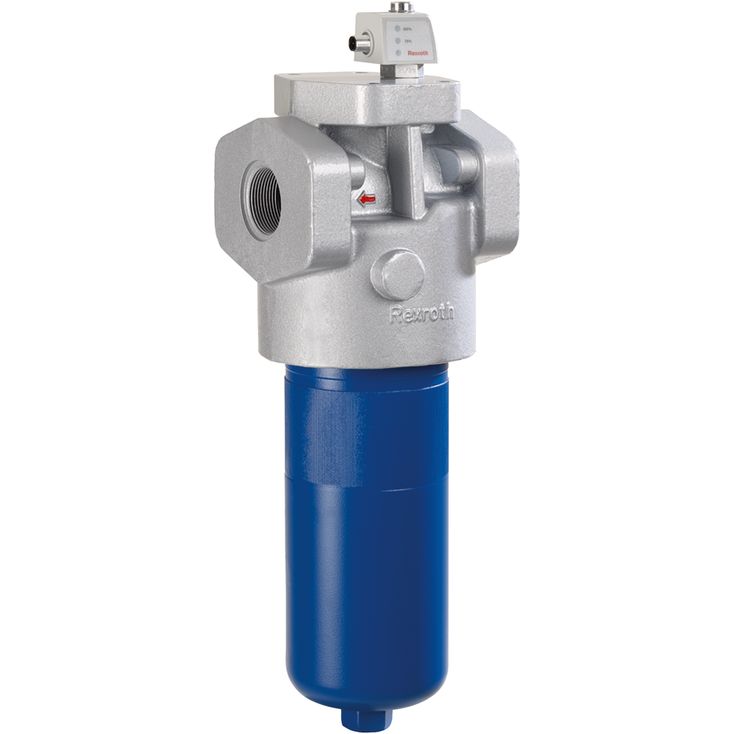
The 445LEN inline filter is suitable for installation into pressure lines.
It basically consists of filter head (1), a screwable filter bowl (2), (size 1000 filter pipe with filter cover), filter element (3) as well as mechanical/visual maintenance indicator (4). In case of filters with low-pressure-differential-stable filter elements (= code letter pressure differential A), there is also an assembled bypass valve (5). Via the inlet, the hydraulic fluid reaches the filter element (3) where it is cleaned. The dirt particles filtered out settle in the filter element (3). Via the outlet, the filtered hydraulic fluid enters the hydraulic circuit.
The filter housing and all connection elements are designed so that pressure peaks – as they may e.g. occur in case of abrupt opening of large control valves due to the accelerated fluid quantity – can be securely absorbed.
As of size 0160, the standard equipment comprises a drain screw (6). With size 1000, the filter bowl has a two-part set-up. In this connection, the filter pipe is secured in the filter head against rotation.
By default, the filter is equipped with mechanical/visual maintenance indicator (4). The electronic switching element (7) which has to be ordered separately is attached to the mechanical/visual maintenance indicator (4) and held by means of a locking ring.
The electronic switching elements with 1 or 2 switching points are connected via a mating connector according to IEC-60947-5-2 or via a cable connection according to EN17301-803.
Variants
Order option Supplementary information -7
The standard outlet is closed by means of a SAE blind flange. The outlet is arranged to the top; in this way, the flow direction is angled by 90° to the top.
Order option Supplementary information -9
The bleeding is arranged at the hexagon of the filter bowl. The drain is located laterally at the filter head vis-à-vis the clogging indicator.