


Бренды
Bladder-type accumulators HAB

Bladder-type accumulators HAB
-
Component series 6X
-
Nominal capacity 1 … 50 l
-
Maximum operating pressure 350 bar
- Component series 6X
- Nominal capacity 1 … 50 l
- Maximum operating pressure 350 bar
- Hydraulic accumulator according to Pressure Equipment Directive 2014/68/EU
- Bladder material for different applications
|
Nominal capacity |
l |
1 | 2.5 | 4 | 6 | 10 | 20 | 24 | 32 | 50 |
|
Weight |
kg |
7 | 10 | 16.5 | 20 | 32 | 53 | 61 | 85 | 123 |
|
Design |
Bladder-type accumulators | |||||||||
|
Installation position |
Bottom fluid connection socket, others upon request | |||||||||
|
Mounting type |
With clamping collars and console | |||||||||
|
Line connection |
Screw-in thread | |||||||||
Function, section
General information
Hydraulic accumulators are hydrostatic devices capable of storing a certain amount of energy in order to release it to the hydraulic system when needed.
Fluids only possess low compressibility; however, gases are highly compressible. The working principle of all gas-loaded hydraulic accumulators is based on this difference.
The difference between bladder and diaphragm type accumulators lies in the type of separator element. Hydraulic accumulators essentially consist of a fluid section and a gas section with a gas-tight separator element.
The fluid section has a connection to the hydraulic circuit.
If a higher liquid pressure is applied to a specific quantity of pressurized gas, the gas volume decreases as the liquid pressure increases, with the gas pressure increasing with the liquid pressure.
If the pressure of the fluid decreases, the fluid is pushed back into the hydraulic system by the expanding gas until the pressure is balanced again.
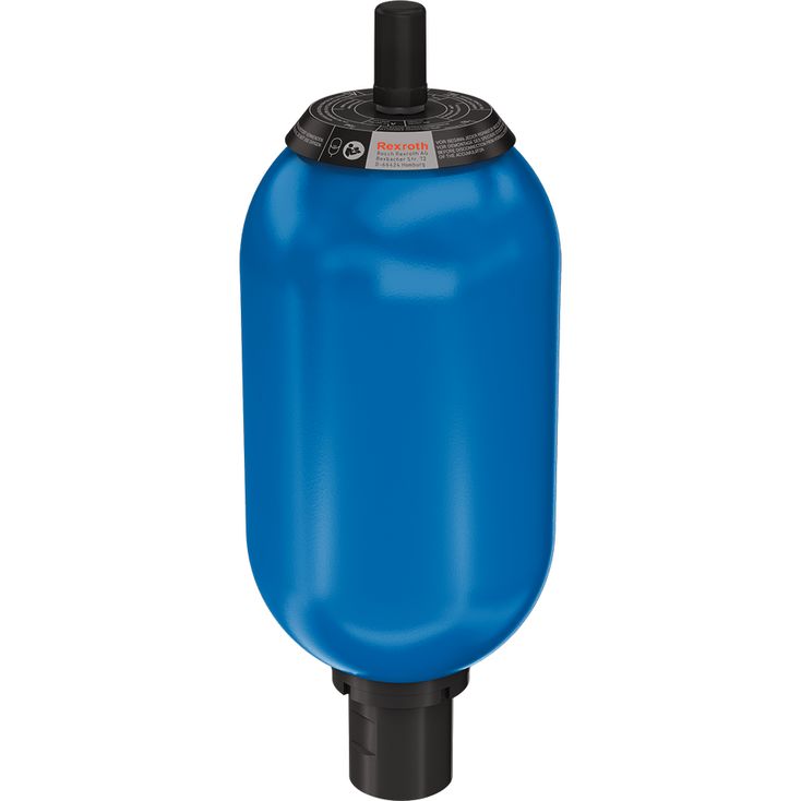
Bladder-type accumulator
Bladder-type accumulators consist of a seamless cylindrical pressure container (1) made of high-strength steel. An elastic bladder (2) mounted inside the container separates the accumulator into a gas side and a fluid side.
Via the gas valve (4), the bladder is filled with nitrogen up to the intended gas filling pressure p0.
The oil valve (3) located inside the oil port of the bladder-type accumulator closes if the pressure on the gas side is higher compared to the fluid side. This prevents the bladder from entering the oil channel and being destroyed.
When the minimum operating pressure is reached, a small fluid volume (approx. 10% of the hydraulic accumulator's nominal volume) should remain between the bladder and the oil valve in order to prevent the bladder from hitting the valve during each expansion process.
The gas valve (4) consists of sealing cap (4.1), gas valve insert (4.2), gas prefill valve body (4.3), and O-ring (4.4). These parts can be replaced individually.
The type cap (7) includes the technical data and features of the hydraulic accumulator.
Symbol

