


Бренды
Command value and ramp module VT-SWMA-1-1X

Command value and ramp module VT-SWMA-1-1X
-
Component series 1X
-
Analog, Modular design
-
For controlling valves with integrated or external electronics
- Differential input for voltage
- 4 internal command values, adjustable and callable
- Adjustable ramp time, sensitivity and zero point
- Actuating signal output
- Ramp time selection with quadrant recognition
- LED displays
- Measuring sockets
|
Component series |
1X | |
|
Type of electronics |
Analog | |
|
Design |
Modul |
General information
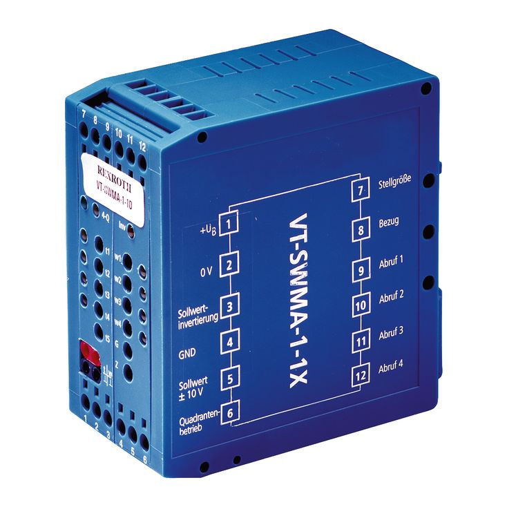
The command value module is snapped onto top hat rails according to EN 60715. The electrical connection is established via screw terminals. The module is operated with 24 V direct voltage. A power supply unit [1] supplies all internally required positive and negative supply voltages. As soon as the power supply unit is in operation, the green LED (“power”) lights up.
Internal command value
The internal command value signal is calculated from the external command value signal available at the differential input [2], a called-up signal and an offset signal (zero point potentiometer “Z” [3]).
The external command value signal can be changed by the potentiometer “G” (amplitude attenuator [4]) from 0 % to approx. 110 %.
Command value call-ups
The call-up signals w1 to w4 [5] also have a setting range from 0 % to 110 %. The call-up signals w1 and w2 have positive, the call-up signals w3 and w4 negative polarity. In this way, two forwards and two backwards movements of the hydraulic drive can be realized without additional circuitry. For applications requiring more than two signals of identical polarity, a command value inversion [6] is provided. If the latter is, for example, operated simultaneously with call-up 3, the call-up signal w3 will also supply a positive control output.
Only one call-up can be operated at a time. If several call-ups are operated simultaneously, the following applies: Call-up “1” has the lowest priority, call-up “4” has the highest priority [7].
Quadrant recognition
If the quadrant recognition [8] is active, the electronics automatically detects the control output polarity [9] and the control output change (up/down) [10] and attributes a ramp time to the current signal state.
|
Ramp time |
Polarity of the control output |
Signal direction |
|
t1 |
+ |
0 % ↗ maximum value (+) |
|
t2 |
+ |
Maximum value (+) ↘ 0 % |
|
t3 |
‒ |
0 % ↘ maximum value (‒) |
|
t4 |
‒ |
Maximum value (‒) ↗ 0 % |
While a signal change is taking place, the LED attributed to the current ramp time is on.
Ramp time call-ups [11]
If the quadrant recognition is not enabled, an own ramp time “t1” to “t4” is assigned to every command value call-up.
While a signal change is taking place, the LED attributed to the current ramp time is on.
Ramp time "t5” [12]
If neither the quadrant recognition nor a call-up is enabled, the ramp time “t5” is always valid. The ramp time is - amongst other things - suitable for an “Emergency Off” function. The valve can then be closed with the defined ramp time “t5”.
Ramp time setting
The current ramp time may be checked at the measuring socket “t” [13]. The ramp time “t1” to “t4” is set by means of the ramp time potentiometer. By means of the activation of a call-up signal, the ramp time signal “t” at the measuring socket is clearly assigned to a ramp time t1 to t4. t5 is assigned to the ramp time signal at the measuring socket if neither a call-up nor the quadrant recognition is enabled. The setting range for the ramp times is selected so that they can be set between 20 ms and 5 s in a reproducible manner.
For setting the ramp time potentiometers, we recommend deactivating the quadrant recognition and operating the call-ups.
The following applies:
|
Value at measuring socket “t" |
U/V |
5 |
3 |
2 |
1 |
0.5 |
0.3 |
0.2 |
0.1 |
0.05 |
0.03 |
0.02 |
|
Current ramp time (±20 %) |
t/ms |
20 |
33 |
50 |
100 |
200 |
333 |
500 |
1000 |
2000 |
3333 |
5000 |
Formula:
; t in ms, U in volt at the measuring socket
Output
The output signal of the ramp generator may be checked at the measuring socket “w” [14]. The subsequent matching amplifier [15] supplies the control signal for the valve at the “control output” output [16].
[ ] = Assignment to the block diagram