


Бренды
Valve amplifiers for proportional pressure valves VT-MSPA1-11-1X

Valve amplifiers for proportional pressure valves VT-MSPA1-11-1X
-
Component series 1X
-
Analog, Modular design
-
For valves:
3DRE(M) 10...-7X
3DRE(M) 16...-7X
ZDRE 10…-2X
(Z)DBE6...-2X
DRE(M) 10(25,32)-6X
3DRE(M) 10...-7X
3DRE(M) 16...-7X
ZDRE 10…-2X
(Z)DBE6...-2X
DRE(M) 10(25,32)-6X
- Differential input for voltage
- Ramp generator with separately adjustable ramp times "up/down"
- Adjustable zero point and sensitivity
- Characteristic curve generator
- Clocked power output stage
- Dither generator
- LED displays for various operating states
- Reverse polarity protection for the operating voltage
|
Component series |
1X | ||
|
Type of electronics |
Analog | ||
|
Design |
Modul | ||
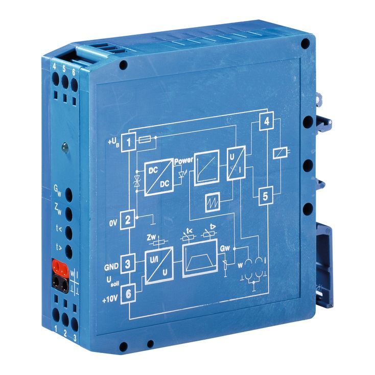
Analog amplifier for controlling pressure valves without electrical feedback. The modular design allows for simple top hat rail mounting as is usual in control cabinets.
Command value input [4]
The module amplifier is controlled by means of a standard command value signal 0 to +10 V. By means of the zero point potentiometer (Zw) [6], a zero point offset can be corrected.
Ramp generator [5]
In the ramp generator [5], the control output incline is limited. Using the trimmer "t <" [7], the time for the increasing command value signal is set and using trimmer "t >" [8], the time for the decreasing command value voltage is set.
Characteristic curve generator [10]
Using the trimmer "Gw" [9], the rated current of 1.6 A for the solenoid is set. In the characteristic curve generator [10], the command value signal is changed so that a linear command value pressure characteristic curve is created.
Clock generator [12]
In the clock generator [12], a frequency for the output stage
adjusted to the command value is generated.
Power output stage [11]-[14]
Using the control output coming from the characteristic curve generator [10] and the clock frequency, the power output stage generates a PWM signal that is fed into the solenoid. The solenoid current is recorded and, in the current controller [11], compared with the control output and the difference is compensated.
Fault recognition [15]
Monitors the solenoid conductors with reference to cable break and short-circuit as well as over-current of the output stage. If there is an error, the green ready for operation display goes out.