


Бренды
Digital valve amplifier for proportional valves without electrical position feedback VT-VSPD-1-2X

Digital valve amplifier for proportional valves without electrical position feedback VT-VSPD-1-2X
-
Component series 2X
-
Digital, Euro-card format
-
For valves:
4WRA, 4WRZ
(Z)DBE, DBE(M)T, DBE(M), DBEP , DBET
DRE 4 K, DRE(M), (Z)DRE, 3DRE(M), 3DREP
4WRA, 4WRZ
(Z)DBE, DBE(M)T, DBE(M), DBEP , DBET
DRE 4 K, DRE(M), (Z)DRE, 3DRE(M), 3DREP
- Valve selection, configuration and parameterization via PC program BODAC
- Serial interface and local bus for up to 32 amplifiers
- Command value input for voltage or current
- Programmable output stage frequency, pilot, step and end current or characteristic curve correction
- Ramp generator
- Digital inputs for calling up preset command value parameters
- Enable input and fault output
- Configurable measuring socket
|
Component series |
2X | ||
|
Type of electronics |
Digital | ||
|
Design |
Euro-card | ||
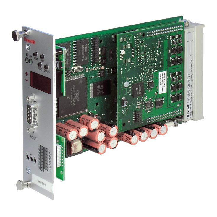
The valve amplifier is set-up as printed circuit board in Europe format 100 mm x 160 mm with daughter board, fitted on both sides.
The central unit of the amplifier is a microcontroller which controls the entire process. Data for configuration, command values and parameters are stored in a FLASH in a non-volatile form.
Four binarily coded digital inputs are used to call up parameter sets (command values) from the memory in which you can store a maximum of 16 sets. A call-up activates the command value for the valve spool position with the related ramp times.
More control inputs have the following functions:
Command value valid:
enable by the parameter set activated by the current call-up (H active)
Enable:
activation of the outputs (acknowledge fault message with low→high edge)
The command value can be preset via digital command value call-ups [5] and/or via analog inputs [1]. The analog input AI4 (b14/b16) is to be used for the command value presetting of ±10 V, the analog input AI6 (b22/b24) for any command value presetting from 4 to 20 mA.
Command values from 0 to +10 V (12...20 mA) control solenoid B.
Command values from 0 to –10 V (4...12 mA) control solenoid A.
The digital command value is added to the analog command value with the correct sign, according to the set call-up.
The command value inputs can be varied by means of software in the signal level.
Apart from the internal ramp generation option, you can also influence the ramp for “up” and “down” from external signals with correct total and correct sign by means of the AI2 (b6/b8) and AI5 (b18/b20) analog inputs.
For the valves, the software configures a step function generator [8] for the realization of the overlap jump if an overlapped control spool is selected.
Enable and error messages
The control is activated by the H level at the enable input. If no command value call-up is active, the digital call-up 0 is set.
Error logics [13] identify any cable break of the command value input for 4 to 20 mA as well as an inactive enable input. If there is an error, a fault message is output to (d22) by means of a low signal and displayed visually by the “OK” LED (LED goes out) on the front plate. It is possible to configure the enable so that an inactive enable input is not displayed as error.
Parameterization and diagnosis
Selection of the valve to be controlled and selection and configuration of the command value input, the ramp generator and the enable input as well as the setting of the command value call-up parameters are effected via the serial interface [17] at the front-side D-Sub socket. Via the local bus [16], up to 32 valve amplifiers can be connected. Via BODAC, every valve amplifier is assigned a bus address. Reconnection of the serial interface cable is not required. Additional information in the instructions 30523-01-B.
In the version with display, configuration, parameterization and diagnosis are possible without PC, directly at the display.
[ ] = Assignment to the block diagram