


Бренды
Valve amplifiers for proportional pressure valves VT-MRMA1-1-1X

Valve amplifiers for proportional pressure valves VT-MRMA1-1-1X
-
Component series 1X
-
Analog, Modular design
-
For valves: (Z)DRS 6
- Command value input for voltage or current
- Ramp generator with separately adjustable ramp times "up/down"
- Adjustable zero point and sensitivity
- Elektronische Endanschläge für den Stellantrieb
- Integrierte Druckschalterfunktion mit einstellbaren Schaltschwellen
- Lageregler mit „Positionssollwert erreicht“-Erkennung
- LED display for the "ready for operation" status, enable and error
- Switchable measuring socket
|
Component series |
1X | ||
|
Type of electronics |
Analog | ||
|
Design |
Modul | ||
General information
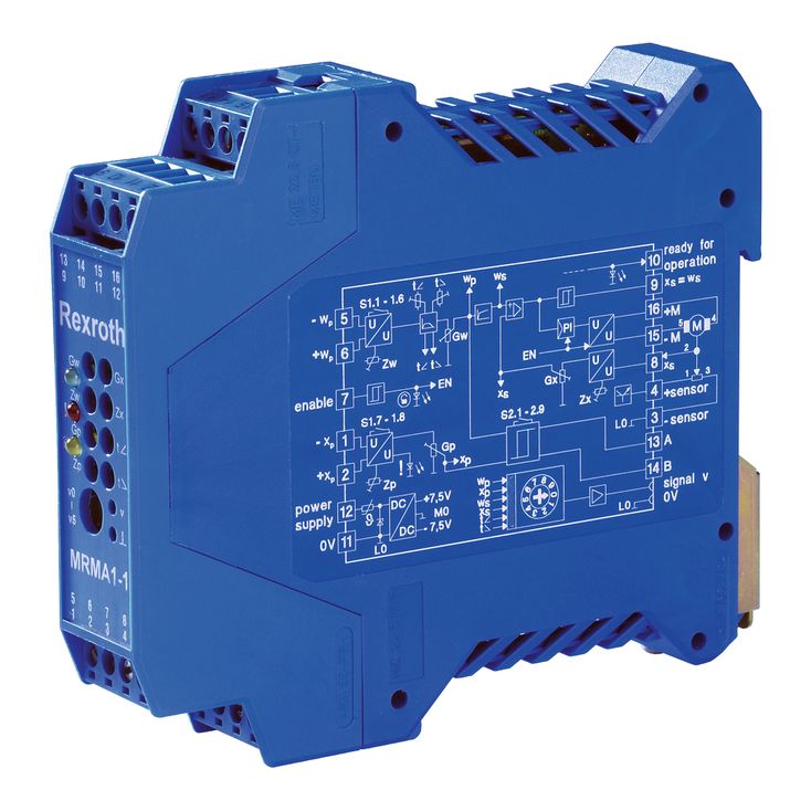
The amplifier module is snapped onto top hat rails according to EN 60715. It is electrically connected via 4 plug-in screw connectors with 4 ports each. The module is operated with 24 V direct voltage.
Power supply unit [1]
An internal power supply unit supplies all internally required positive and negative supply voltages.
Pressure command value presetting [2]
The internal pressure command value signal is generated from the external pressure command value signal available at input [2] and the zero point offset [2] (Zw zero point potentiometer on the front side). If the pressure command value increases/decreases, the pressure rises/falls. The differential input can be configured into a 4 to 20 mA current input via DIL switches S1.1 to S1.6 (see commissioning instructions).
|
Standard values |
Current input |
Differential input |
Command value at measuring socket "v" (position 0) |
|
0 % |
4 mA |
0 V |
0 V |
|
100 % |
20 mA |
+10 V |
+10 V |
A cable break in a pressure command value line will be detected ("ready for operation" output) and deactivate the output stage.
Ramp generator [3]
In the ramp generator [3], a provided step signal is turned into a ramp-shaped output signal. The ramp time relates to a pressure command value modification of the input signal of 100 %. The ramp time is not extended or shortened by the downstream pressure command value attenuator [4].
The ramp times for pressure increase or pressure reduction can be set separately on the front side of the module using potentiometers "t <" and "t >". The current ramp time values can also be checked or pre-set via the switchable measuring socket (also located on the front side).
Information on ramp time adjustment:
|
Value at measuring socket "v" |
Usocket/V |
10 |
5 |
3 |
2 |
1 |
0.5 |
0.1 |
0.05 |
0.03 |
0.02 |
0.01 |
|
Current ramp time (±20 %) |
t/s |
0.1 |
0.2 |
0.33 |
0.5 |
1 |
2 |
10 |
20 |
33.3 |
50 |
100 |
Calculation of the ramp times:

The following applies:
U = Voltage in volt at measuring socket "v"
t = Ramp time in seconds for upwards and downwards ramp
Pressure command value attenuator Gw [4]
The Gw potentiometer acts as an attenuator [4] and determines the maximum internal pressure command value. The setting range lies between 0 % and 130 %.
Linearization of the valve characteristic curve [5]
The linearization [5] is used to compensate the non-linear valve characteristic curve. The required valve position command value is generated from the pressure command value.
Amplitude limiter [6]
The amplitude limiter [6] limits the internal valve position command value to +110 % and –5 %.
Actual valve position value acquisition [12]
A voltage output is used to supply the position transducer. The actual valve position value fed back by the position transducer can be corrected using the Zx zero point potentiometer and the Gx sensitivity potentiometer. The internal actual position value signal generated this way is provided to the valve position controller [7] for further processing. Cable breaks in the position transducer lines are detected via the fault recognition [8].
Electronic limit stop
The electronic limit stops are a functional part of actual valve position value acquisition [12].
The adjustable stroke of the valve is mechanically limited. The used working range is within these mechanical stops. To prevent moving into the mechanical stops when this is not intended (e.g. During setting), so-called "electronic stops" which are within these limits have been realized for safety purposes. The valves are prevented from moving beyond these limits by deactivation of the output stage. The electronic stops are only effective if sensor and motor are correctly wired.

Valve position controller [7]
The valve position controller [7] generates the control output for the clocked output stage on the basis of the position control deviation. The position controller has been optimized for a special valve type.
Output stage [10]
The output stage [10] generates the clocked control voltage for the DC motor acting as actuating element in the pressure reducing valve. The output stage output is short-circuit-proof. The output stage is de-energized in case of an internal fault signal [8] or if not enabled [11].
"Position command value reached" recognition [9]
A "position command value reached" output is provided for as auxiliary process variable. This output is connected with 24 V operating voltage when the control deviation from the valve position command value and the regulated actual valve position value are ≤ 5 % of the nominal stroke and the internal ramp output signal corresponds to the provided pressure command value.
Fault recognition [8]
The following is monitored:
Cable break of pressure command value lines
Inversion of the pressure command value lines
Cable break of the position transducer connecting lines
Short-circuit of the position transducer supply at L0 (0 V)
Thanks to the integrated motor protection the following is detected:
Inversion of the motor lines (positive feedback)
Jammed valve actuator
Cable break of the motor lines
If there is no error, the green "ready for operation" LED on the front side is lit and the "ready for operation" output is connected to 24 V operating voltage.
Motor protection
The motor protection is a functional part of the fault recognition [8]. To ensure the correct functioning of the valve actuator, the adjustment time required for each pressure adjustment process is monitored. If an internally set maximum adjustment time (approx. 4 s) is exceeded, the output stage is deactivated to prevent the motor from being damaged by continuous application of current.
The "ready for operation" output is connected to 0 V and the green LED on the front side goes out. After the cause of error has been eliminated, the electronics can be reactivated by resetting and enabling it.
The motor protection detects the following:
Inversion of the motor lines (positive feedback)
Cable break of the motor lines
Jammed valve actuator
Enable function [11]
The enable function [11] can be used to activate both the position controller and the output stage via the external control. The enable signal is indicated by a yellow LED on the front side of the module.
Internal controller and output stage enable
The controller and the output stage are enabled if the external enable [11] has been set and the electronics are "ready for operation", i.e. fault recognition [8] does not diagnose any error.
Actual pressure value input [13]
The internal actual pressure value signal is generated from the signal available at actual pressure value input [13] and the zero point offset (Zp zero point potentiometer on the front side). The Gp sensitivity potentiometer can be used to compensate tolerance-related variations of the pressure transducer. The input can be configured either as 0.5 to 5 V voltage input or 4 to 20 mA current input via the DIL switches S1.7 and S1.8 (see commissioning instructions) and a corresponding adjustment using the Zp zero point potentiometer and Gp sensitivity.
Notice: If the input is configured as 4 to 20 mA input and if the actual pressure value input is controlled in series with another separate external current input, the module electronics supplies an offset current at terminal 1. This must be taken into account when adjusting the external current input.
The following is monitored at the actual pressure value input (depending on the property of the pressure transducer electronics):
Cable break of the actual pressure value lines
Inversion of the actual pressure value lines
Cable break of the pressure transducer's operating voltage
Cable break of the pressure transducer's ground
If one of these errors is detected at the actual pressure value input, both pressure switch signals A and B are switched with 0 V and the red LED "!" on the front side of the amplifier module is lit.
Pressure switch function [14]
The integrated pressure switch [14] compares the internal actual pressure value to a window which can be individually adjusted by the pressure command value (DIL switches S2.1 to S2.9). Depending on whether the actual pressure value falls below the lower limit or exceeds the upper limit, the corresponding pressure switch signal A or B falls to 0 V. If the actual pressure value is within the pressure command value window, both pressure switch signals are connected to 24 V operating voltage.
Exception: In case of a cable break of one of the two actual pressure value lines both signals A and B fall to 0 V.
(adjustment of the pressure switch thresholds via DIL switch S2, see commissioning instructions)
Measuring point switch-over [15]
The measuring sockets v and ⊥ on the module front side can be used to check various internal measuring points (v0 to v5). The measuring points are selected via the measuring point selector switch [15] on the housing front panel (see Adjustment elements).