


Бренды
Valve amplifiers for proportional flow control valves VT-MRPA1-151-1X
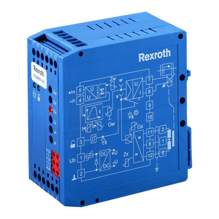

Valve amplifiers for proportional flow control valves VT-MRPA1-151-1X
-
Component series 1X
-
Analog, Modular design
-
For valves: 2FRE10-4X, 2FRE16-4X
- Differential input for voltage
- Ramp generator with separately adjustable ramp times "up/down"
- Adjustable zero point and sensitivity
- Enable input
- Cable break detection for actual value cable
- Reverse polarity protection for the operating voltage
- LED displays for ready for operation and enable
|
Component series |
1X | ||
|
Type of electronics |
Analog | ||
|
Design |
Modul | ||
General information
The amplifier modules are snapped onto top hat rails according to EN 60715. The electrical connection is established via screw terminals. The modules are operated at 24 V direct voltage.
Power supply unit [1]
The amplifier modules have a power supply unit with making current limiter. This unit supplies all internally required positive and negative supply voltages. The making current limiter prevents high making current peaks.
Command value presetting
The internal command value signal is
calculated from the total [3] of the external command value signal available at the differential input [2] and the zero point offset (zero point potentiometer "Zw").
A positive command value results in a current increase in the solenoid and thus a pressure increase in the valve.
Enable function [11]
The enable function enables the current output stages and forwards the internal command value signal to the ramp generator. The enable signal is indicated by an LED on the front plate. If enable is connected, the internal command value is changed (with any kind of command value presetting) by the set ramp time. Thus, a controlled valve does not open abruptly.
Ramp generator [4]
The ramp generator limits the incline of the control output. The amplitude attenuator does not extend or shorten the ramp time.
Information on ramp time settings and measurement:
|
Value at measuring socket |
U/V |
5 |
3 |
2 |
1 |
0.5 |
0.3 |
0.2 |
0.1 |
0.05 |
0.03 |
0.02 |
|
Current ramp time (±20 %) |
t/ms |
20 |
33 |
50 |
100 |
200 |
333 |
500 |
1000 |
2000 |
3333 |
5000 |
Formula for calculation of the ramp times:
t in ms, U in volt at the measuring socket
Amplitude attenuator [5]
By means of the amplitude attenuator "Gw", the maximum value can be adjusted to the hydraulic requirements in a range between 0 and 100 %.
Amplitude limiter [6]
The internal command value is limited to 0 % and 110 %.
Oscillator [9]
The oscillator creates the control signal for the inductive position transducer.
Demodulator [10]
The demodulator supplies the actual value signal of the control spool position from the position transducer signal.
+100 % ≙ +10 V at measuring socket "x"
Controller for the control spool position [7]
The position controller is intended to minimize the valve hysteresis and is optimized in a valve-specific manner.
Current output stage [8]
The current output stage creates the clocked solenoid current for the proportional valve. The solenoid current is limited to approx. 1.85 A. The output stage output is short-circuit-proof. The output stage is de-energized in case of an internal fault signal or if the enable signal is missing.
Fault recognition [14]
The position transducer cable is monitored for cable break and short-circuits on the primary side as well as for over-currents at the output stage.
[ ] = Assignment to the block diagram