


Бренды
Valve amplifiers for proportional directional valves VT-MRPA2-1-1X, VT-MRPA2-2-1X
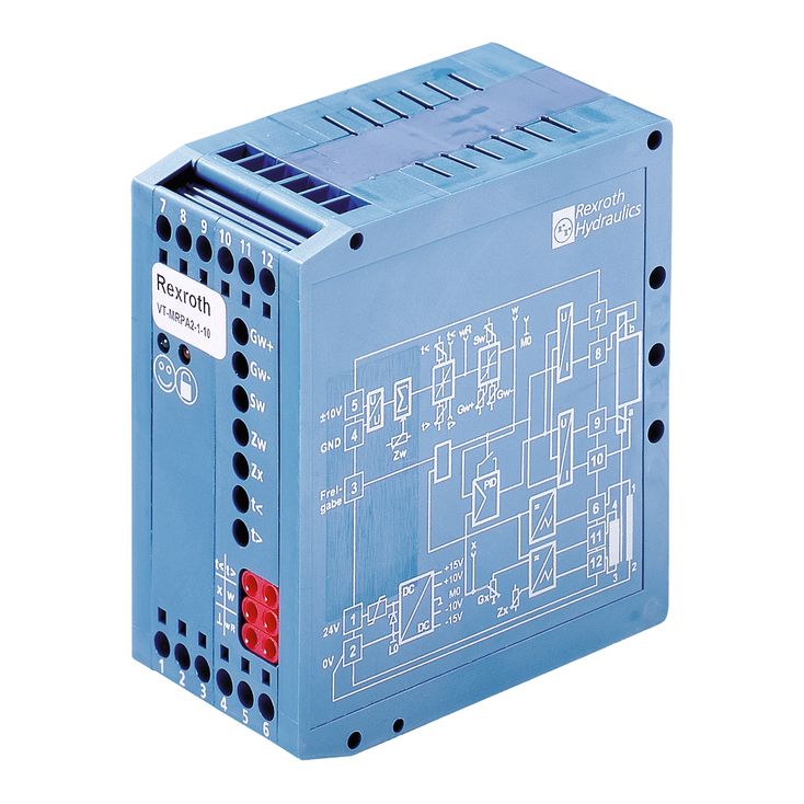

Valve amplifiers for proportional directional valves VT-MRPA2-1-1X, VT-MRPA2-2-1X
-
Component series 1X
-
Analog, Modular design
-
For 4/3-way proportional directional valves 4WRE (with two solenoids)
- Differential input for voltage
- Ramp generator with separately adjustable ramp times "up/down"
- Adjustable zero point and sensitivity
- Adjustable step level
- Cable break detection for actual value cable
- Reverse polarity protection for the operating voltage
- LED displays for ready for operation and enable
|
Component series |
1X | ||
|
Type of electronics |
Analog | ||
|
Design |
Modul | ||
Power supply unit [1]
The amplifier modules have a power supply unit with making current limiter. This unit supplies all internally required positive and negative supply voltages.
Command value presetting
The internal command value signal is calculated from the total [3] of the external command value signal available at the differential input [2] and the zero point offset (zero point potentiometer "Zw").
A positive command value results in a current increase in the "b" solenoid and thus a flow in the valve from P to A and from B to T.
A negative command value results in a current increase in the "a" solenoid and thus a flow in the valve from P to B and from A to T.
Enable function [11]
The enable function enables the current output stages and forwards the internal command value signal to the ramp generator. The enable signal is indicated by an LED on the front plate. If enable is connected, the internal command value is changed (with any kind of command value presetting) by the set ramp time. Thus, a controlled valve does not open abruptly.
Ramp generator [4]
The ramp generator limits the incline of the control output. The downstream step functions and amplitude attenuators do not extend or shorten the ramp time.
Information on ramp time setting and measurement:
|
Value at measuring socket |
U/V |
5 |
3 |
2 |
1 |
0.5 |
0.3 |
0.2 |
0.1 |
0.05 |
0.03 |
0.02 |
|
Current ramp time (±20 %) |
t/ms |
20 |
33 |
50 |
100 |
200 |
333 |
500 |
1000 |
2000 |
3333 |
5000 |
Formula for calculation of the ramp times:
t in ms, U in volt at the measuring socket
Characteristic curve generator [5]
Using the adjustable characteristic curve generator, step level and maximum values for positive and negative signals can be set and adjusted to the hydraulic requirements. The actual development of the characteristic curve through the zero point is not stepped but linear.
Amplitude limiter [6]
The internal command value is limited to approx. ±110 % of the nominal range.
Oscillator [9]
The oscillator creates the control signal for the inductive position transducer.
Demodulator [10]
The demodulator supplies the actual value signal of the control spool position from the position transducer signal.
±100 % ≙ ±10 V
Controller for the control spool position [7]
The position controller is optimized in a valve-specific manner.
Current output stage [8]
The current output stage creates the clocked solenoid current for the proportional valve. The solenoid current is limited to 2.4 A to 2.6 A per output. The output stage outputs are short-circuit-proof. The output stages are de-energized in case of an internal fault signal or if the enable signal is missing.
Fault recognition [14]
The position transducer cable is monitored for cable break and short-circuits on the primary side as well as for over-currents at the output stage.
[ ] = Assignment to the block diagram