


Бренды
Valve amplifiers for proportional flow control valves VT-VRPA1-150-1X
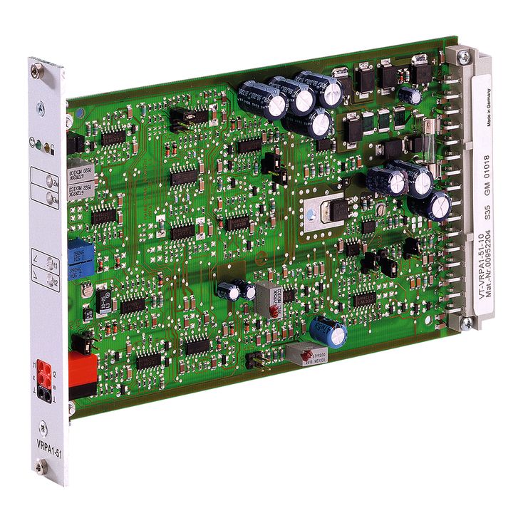

Valve amplifiers for proportional flow control valves VT-VRPA1-150-1X
-
Component series 1X
-
Analog, Euro-card format
-
For valves: 2FRE 6
- Differential input, switchable from voltage to current input
- Two non-isolated command value inputs
- Enable input and "ramp off" input
- Amplitude, zero point and adjustable ramp time
- Reverse polarity protection for the operating voltage
- Outputs for command value and actual value
- LED display for "ready for operation"
|
Oscillator frequency |
f |
kHz |
2.5 ±10 % | |
Limitation and position controller
From the output of the ramp generator [3], the command value voltage reaches the "Gw" potentiometer which is accessible through the front plate and serves as attenuator. It can also be used to set the maximum flow of the valve. The downstream limiter [7] limits the command value to 105 % or –5 % (e.g. at excessive command value voltage or by adjustment of the potentiometer for zero point "Zw" and basic value "Gw") to prevent the valve spool from hitting the mechanical end positions. The output signal of the limiter [7] is the position command value which is supplied to the PID controllers [8] and via an output stage [17] also to measuring socket "w" on the front plate of the card as well as to port 28c at the connector strip X1 (command value after ramp and limiter). A voltage of +6 V at command value measuring socket "w" corresponds to a command value of +100 %. The PID controller has been especially optimized for DBETR and FRE valves. In the controller, the position command value and the actual position value are compared; in case of a difference, a corresponding control output is forwarded to the current output stage [13] the output signal of which controls the proportional solenoid of valve.
Position sensing
The position transducer electronics consist of an oscillator [14] with downstream driver [15] for controlling the inductive position transducer and a demodulator [16] for analyzing the position transducer signal (actual value). The oscillator frequency is approx. 2.5 kHz. The inductive position transducer must be connected as throttle circuit with mid sensing. The position transducer electronics have been adjusted at the factory. Very long or capacitive position transducer lines may require readjustment of the zero point (via potentiometer "Zx"). The actual value (corresponds to the valve spool position) can be measured at the actual value measuring socket.
Notice:
The actual value signal is output in inverted form as compared to the command value. A path of 100 % corresponds to –6 V at the actual value measuring socket and at port 32a of the connector strip X1.
Enable input
With a signal of > 10 V at enable input 20a, the output stage and I controller are enabled (indication by the yellow LED at the front plate). By setting jumper X3, these are independently and permanently enabled by the signal at the enable input. The switching input will then be ineffective.
[ ] = Assignment to the block diagram
When using an external time potentiometer, the internal potentiometers for the ramp times must be set to maximum (voltages at the "t1" and "t2" measuring sockets approx. 20 mV). The maximum ramp time is reduced as the resistance value of the external potentiometer is switched in parallel to that of the internal potentiometer (approx. 500 kΩ). In this case, the ramp times for upwards and downwards ramp cannot be set separately.
By applying a voltage >10 V to the "Ramp off" switching input or setting the plug-in jumper X4, the ramp time is set to its minimum value (approx. 15 ms). The switching input will then be ineffective. The minimum value is then valid for both directions.
Calculation of the ramp times
Jumper X9 plugged (ramp time "short")

Jumper X8 plugged (ramp time "long")

The following applies:
U = Voltage in volt at measuring socket "t1" or "t2"
t = Ramp time in seconds for upwards and downwards ramp
Ramp function
The down-stream ramp generator [3] generates a ramp-shaped output signal from a given step-shaped input signal. The time constants of the output signal (ramp times) can be adjusted using the "t1" (upwards ramp) and "t2" (downwards ramp) potentiometers accessible through the front plate. The specified maximum ramp time refers to a command value step of 100 % and may be approx. 5 s or 50 s depending on the jumper setting (X8, X9). If a command value step of less than 100 % is switched to the ramp generator input [3], the ramp time will be correspondingly shorter. The current ramp time can be checked at the "t1" (upwards ramp) and "t2" (downwards ramp) measuring sockets.
For detailed information, refer to Technical data
Power supply unit
After application of the operating voltage, the internal power supply unit [6] creates a voltage of ±9 V as compared to measurement zero (M0). Measured against load zero (L0), it is raised by +9 V. The voltages +9 V and –9 V (–9 V corresponds to L0) are fed to the connector strip X1 and can be used externally (e.g. for a command value potentiometer). The maximum load capacity is 25 mA.
Ready for operation
The amplifier card is ready for operation if the following conditions are met:
Operating voltage > 20 V
No asymmetry of internal supply voltages
No cable break in position transducer lines
no short-circuit in solenoid conductors
The "ready for operation" status is indicated by the green LED on the front plate.
Command value
The command value voltage is either specified directly, by the regulated voltage +9 V of the power supply unit [6] or via an external command value potentiometer. For the "Command value 1" input, +9 V ≙ +100 % and for the "Command value 2" input, +6 V ≙ +100 %. The reference point for the command value inputs 1 and 2 is always M0 (18ac). Command value input 3 is a differential input [1] (0 to +10 V). It can be configured by setting jumpers as current input (0 to 20 mA or 4 to 20 mA). If the command value is specified by external electronics with a different reference potential, the differential input has to be used.
When disconnecting or connecting the command value voltage, it has to be ensured that both signal lines are in each case separated from or connected with the input. Before they are forwarded, all command values will be added up according to their absolute value and their sign [2]. Using the "Zw" potentiometer, offset voltages in the command value branch can be compensated.
External time potentiometer

External command value potentiometer (with 9 V command value input)
