


Бренды
Valve amplifier for adjusting the flow of axial piston pumps VT 5035-1X
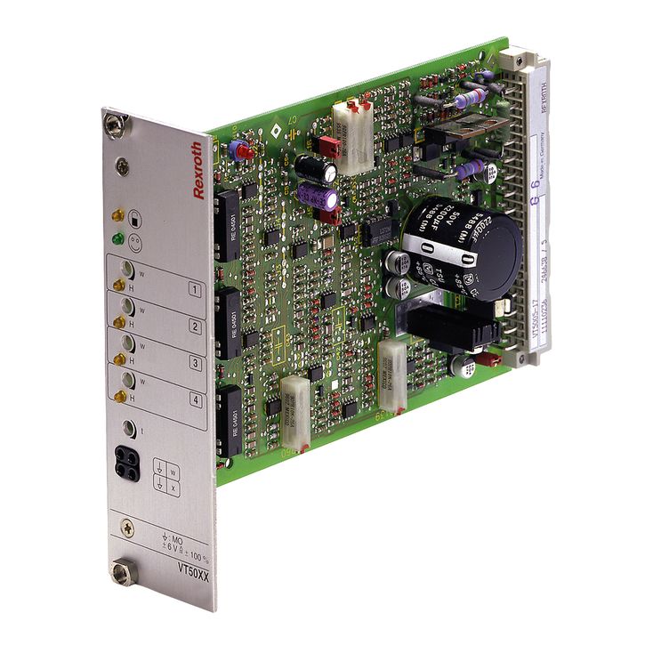

Valve amplifier for adjusting the flow of axial piston pumps VT 5035-1X
-
Component series 1X
-
Analog, Euro-card format
-
For flow adjustment of the variable displacement axial piston pumps A4VSO and A4VSG
- Differential input for voltage
- Four callable command value inputs, input for ramp time
- Controller for the pump swivel angle
- Controlled output stages
- Oscillator/demodulator for inductive position feedback
- Reverse polarity protection for the operating voltage
- Enable input
|
Component series |
1X | ||
|
Type of electronics |
Analog | ||
|
Design |
Euro-card | ||
The printed circuit board is used for the electric flow control of an AV4VSO and AV4SG with EO1 and EO2 adjustment or an AVCSG with EO2 adjustment.
The amplifier controls the proportional valve of the swivel angle actuating cylinder and controls its position analogously to the specified command value. The swivel angle position is recorded as actual value.
Using the command value inputs 1 to 4, command values can be retrieved [1] by actuating the related relays (K1 to K4). The command value voltage is either specified directly, by the regulated voltages ±9 V of the internal power supply unit [10] or via an external command value potentiometer. For these inputs, ±9 V ≙ 100 %. Reference potential for command values 1 to 4 is M0. If these four command value inputs are directly connected to the regulated voltages ±9 V, four different command values can be set at the "w1" to "w4" potentiometers. When external command value potentiometers are used at these inputs, the internal potentiometers function as attenuators or limiters unless they have been set to the maximum.

The LEDs "H1" to "H4" indicate which command value is just being called. If more than one command value is called at a time, the input with the highest number will take priority.
Example: If command value 1 and command value 3 are activated simultaneously, command value 3 will take effect.
Another output of the card supplies a supply voltage for the command value call-ups which can be switched from +9 V to –9 V by means of the relay K6).
All relays on the card are switched with 24 VDC (smoothened).
The command value input 5 is a differential input (0 to ±10 V). If the command value is specified by external electronics with a different reference potential, this input has to be used. When disconnecting or connecting the command value voltage, it has to be ensured that both signal lines are in each case separated from or connected with the input.
Before they are forwarded, all command values will be added up according to their absolute value and their sign [3].
The down-stream ramp generator [4] generates a ramp-shaped output signal from a given step-shaped input signal. The time constant of the output signal can be adjusted using the "t" potentiometer. The specified ramp time refers to a command value step of 100 % and may be approx. 1 s or 5 s depending on the jumper setting (J5, J6). If a command value step of less than 100 % is switched to the ramp generator input, the ramp time will be correspondingly shorter.

Notice:
When using an external time potentiometer, the internal potentiometer for the ramp time must be set to maximum. The maximum ramp time is reduced as the resistance value of the external potentiometer is switched in parallel to that of the internal one (ca. 500 kΩ).
By switching the relay K5 or by an external jumper, the ramp time is set to its minimum value (ca. 30 ms).
The output signal of the ramp generator [4] is the swivel angle command value and is supplied to the PID controller [5], the "w" measuring socket on the front plate of the card and port 4a (command value after ramp/external limiting potential). A voltage of –6 V at command value measuring socket "w" corresponds to a command value of +100 %.
The PID controller has been especially optimized for the specified pump types. The current output stages are controlled depending on the difference between swivel angle command value and actual swivel angle value. A positive command value signal at the amplifier input actuates the output stage for solenoid "a", a negative command value signal the output stage for solenoid "b".
The inductive position transducer [11] detects the actual swivel angle value. The AC voltage signal of the position transducer is converted in the oscillator/demodulator [9] and returned to the PID controller as actual swivel angle value.
The zero point of the position transducer (actual value zero point) can
be adjusted by means of the "Zx" potentiometer (on the printed circuit board). The amplification of the actual swivel angle value has been calibrated at the factory and must not be changed (±6 V ≙ max. swivel angle position)
With a signal of > 8.5 V at the enable input, the output stages are enabled (indication by the yellow "H11" LED on the front plate). By setting jumper J7, the output stages are permanently enabled irrespective of the enable input status. The enable input will then be ineffective.
In case of fault-free operation, the "H12" LED (ready for operation) is illuminated; in detail if:
the enable signal is applied,
the internal ±9 V voltage supply functions (amplitude and symmetry),
no short-circuit of the solenoid conductors and
no cable break in position transducer lines.
In case of fault, the two output stages are immediately de-energized, the controller is switched off and the "Ready for operation" message is reset. After correction of the fault, the card is immediately functional again; the "H12" LED lights up again.
[ ] = Assignment to the block diagram