


Бренды
Float switch with switching contacts and temperature contact, with resistance measuring chain / resistance thermometer, with display and control unit ABZMS-41
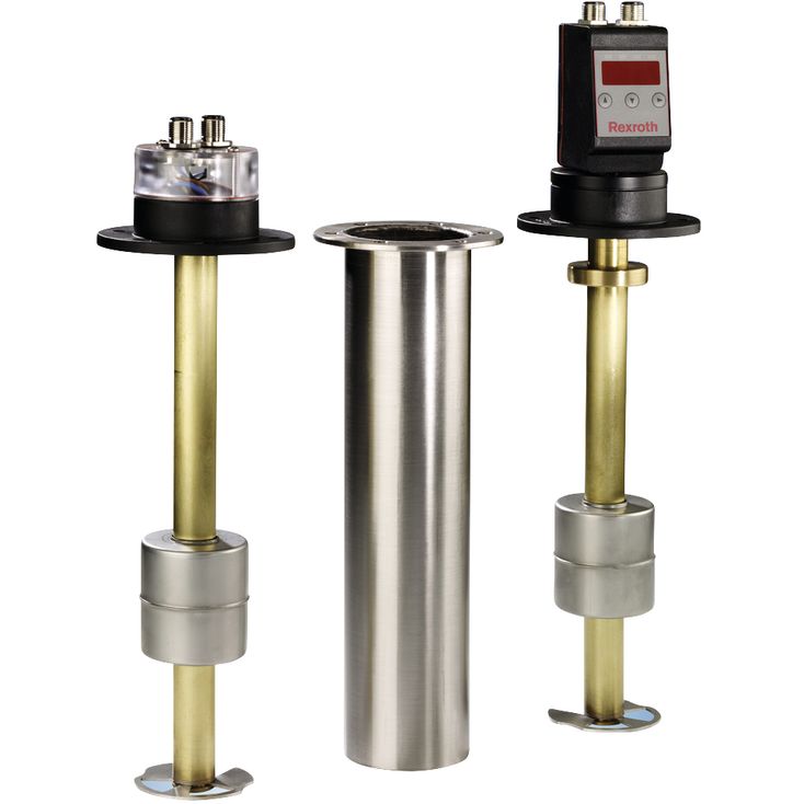

Float switch with switching contacts and temperature contact, with resistance measuring chain / resistance thermometer, with display and control unit ABZMS-41
-
Component series 1X
|
Medium temperature range |
°C |
-20 … +80 | |||||
|
Ambient temperature range |
M…; RTA |
°C |
-20 … +85 | ||||
|
D1; D2 |
°C |
-20 … +70 | |||||
|
Installation position |
vertical ±10° | ||||||
|
Material |
Sliding tube |
Cu alloy | |||||
|
Sliding tube Ø |
mm |
20 | |||||
|
Protective pipe |
Stainless steel 1.4301 | ||||||
|
Protective pipe Ø |
mm |
60.3 | |||||
|
Float |
Stainless steel 1.4571 | ||||||
|
Flange |
PA12 + 25GF (25 % glass fiber) | ||||||
|
Seal material |
Klinger C-4400 | ||||||
|
Maximum switching point L1 |
mm |
1140 | |||||
|
Maximum weight with order length |
mm |
370 | 500 | 800 | 1000 | 1200 | |
|
kg |
0.5 | 1.3 | 1.8 | 2 | 2.2 | ||
Float switches are switching devices operated by a float moved by fluid. These are used to control fluid levels in power unit tanks.
Three series are available:
Function level
Level contacts:
The sliding tubes contain the adjustable reed contacts (normally closed and normally open) that are switched by the permanent magnets installed in the float.
If with falling oil level, the float reaches the switching points, the contacts are operated magnetically. The spool positions of the contacts are maintained until the float exceeds the switching points again as the oil level rises.
The switching points can be adjusted in the device.
By turning the contacts by 180°, the switching function changes; the contact type normally closed contact becomes a normally open contact or vice versa.
Resistance measuring chain:
The sliding tube contains the resistance measuring chain (contact distance 5 mm / resolution) for the continuous recording of the filling level. If the individual reed contact is switched (closed) by the permanent magnet contained in the float, one resistance is in each case activated. The added resistance value is converted in 4 … 20 mA by a transformer.
Function temperature
Temperature contact:
At the lowest point within the sliding tube, the bi-metal temperature contacts are attached to the board and secured by means of a shrink tube (the same procedure is used for the versions with temperature sensor PT 100 and resistance thermometer with analog output 4-20 mA). If the desired temperature switching point is reached, the bi-metal contact is opened or closed.
Temperature sensor PT100:
The PT100 consists of a temperature sensor guaranteeing continuous temperature recording. In this connection, the max. cable length of 6 m is to be observed.
Resistance thermometer with measuring transducer, output 4 … 20 mA:
The resistance thermometer PT100 with measuring transducer is also attached in the sliding tube at the board. The temperature- dependent signal is converted into a linear current change of 4 … 20 mA.
Function display and control unit (version D)
The microprocessor-controlled display and control unit processes the analog input signals for the analysis of the level and temperature control. The level and temperature settings can be made at the control unit in a simple menu tree by means of pushbuttons and read at the LED display.
The display and control unit has a red, four-digit sevensegment LED display and 3 pushbuttons for the operation as well as up to 4 LEDs integrated in the front plate for displaying alarm conditions.
The device has moreover four freely adjustable PNP switching outputs plus the adjustable switch-back points (version D1) and alternatively (version D2) two freely programmable PNP switching outputs and 2 x 4 … 20 mA output for the continuous measurement of oil level and temperature. The switching conditions are shown in the display.
The 4 … 20 mA output can optionally be changed to 0 … 10 V, 2 … 10 V or 0 … 5 V.
In the display, the measured temperature or filling value will be shown in the desired unit (°C, °F, L, cm, %, inch or mm) according to the setting. By default, the temperature display is set to °C.
During the setting and/or programming of the corresponding process parameters, the parameter values and/or the related menu items will be shown in the display.
In case of an energy supply failure, all input values will be stored, the min/max values can be retrieved from a permanent memory, if necessary.
Parameterization
The menu navigation is based on the VDMA standard sheet for fluid sensors 24574-1.
The operating menu is designed hierarchically, as tree structure.
That means that frequently used functions and adjustment points can be accessed very quickly and rarely used menu items can be found in a sub-menu.
Using the ▲ and ▼ keys, the corresponding parameter is set and/or the next menu item is displayed.
Using the ► key, the marked menu item is selected and/or the set parameter is accepted and saved.
The parameter may be a numerical value and a selection of functions (e.g. NO [output as normally open contact], NC [output as normally closed contact] or i1 [analog output 4 … 20 mA]).
After confirmation of a parameter or selection of a function using the ► key, the display switches back to the current menu item. Then, you can display the next menu item using ▲ and ▼ and select it using ►.